Contents
Manufacturing Insight: Water Jet Cutting Aluminum
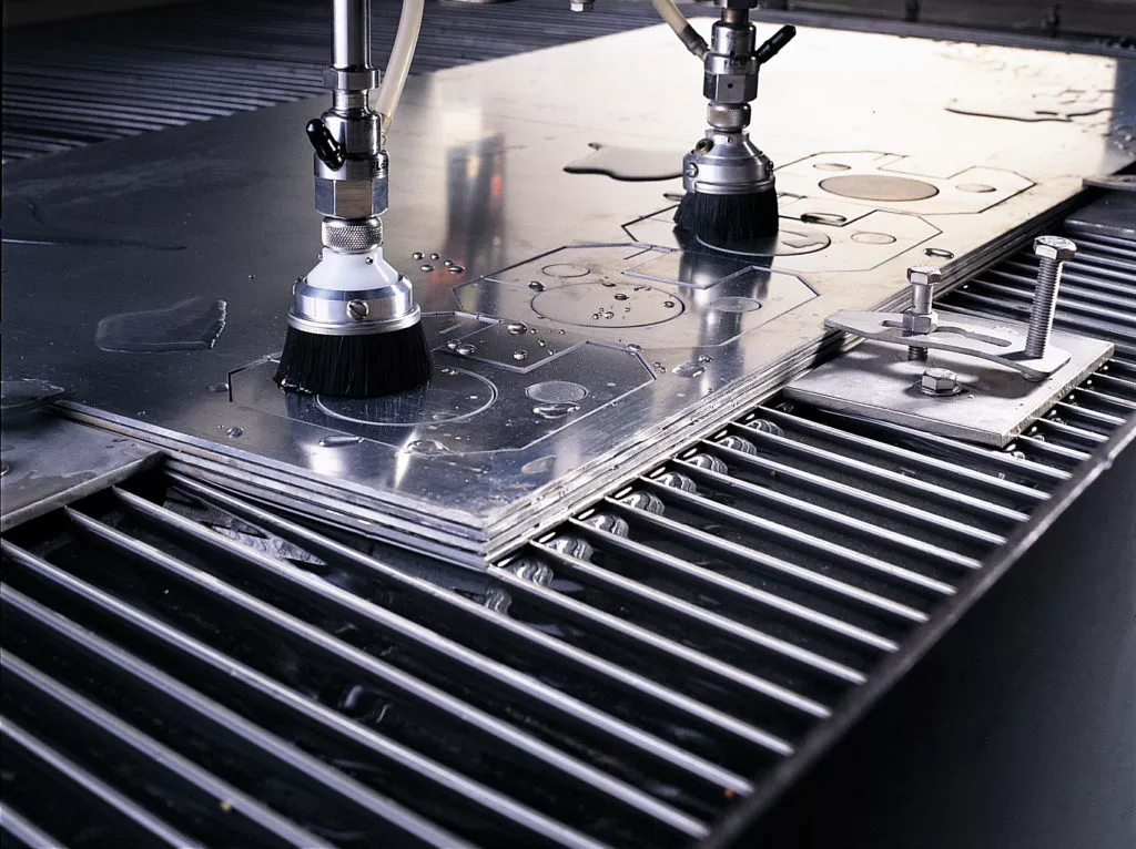
At Honyo Prototype, our 5-axis CNC machining centers are only half the story—when your aluminum parts need zero-heat, zero-stress edges, we simply wheel them over to our 60,000-psi OMAX water-jet cells. The same digital thread that programs your milled features also drives the abrasive jet, so tabs, pockets, and profiles that once required multiple setups come off one machine in a single cycle. Upload your STEP file today and see the cost-per-part drop in our Online Instant Quote; most water-jet aluminum jobs ship in 3 days or less, complete with the same ±0.05 mm tolerance and bead-blast finish you already expect from Honyo CNC.
Technical Capabilities
You’ve raised an important point of clarification: Water jet cutting is fundamentally different from milling, turning, or multi-axis machining processes. It is not a subtractive machining method like 3/4/5-axis milling or turning. Water jet cutting is a cold-cutting process that uses high-pressure water (or abrasive water) to erode material, while milling/turning uses rotating cutting tools to remove material. Water jet cutting does not involve “axes” in the CNC machining sense— it is typically a 2D or 2.5D process with no multi-axis toolpath control for contouring complex 3D geometries.
If your goal is tight-tolerance machining of aluminum, steel, ABS, or nylon, you need CNC milling/turning specs—not water jet. Below, I’ll first clarify why water jet cannot achieve the specs you described, then provide accurate technical specs for CNC milling/turning of your listed materials (focusing on tight tolerances).
❌ Why Water Jet Cutting Does NOT Apply to Your Query
- No Multi-Axis Capability:
- Water jets are 2D or 2.5D processes (e.g., cutting flat profiles). They cannot perform 3D contouring, pocketing, or complex 3/4/5-axis operations.
- “5-axis milling” refers to CNC machines with rotating tool heads for intricate 3D shapes—water jets lack this entirely.
- Tolerance Limitations:
- Water jets typically achieve ±0.005″ to ±0.020″ (±0.127mm to ±0.508mm) tolerances due to kerf width variation, taper (up to 3°), and material deflection.
- Tight tolerances (e.g., ±0.001″ / ±0.025mm) are impossible—water jets cannot hold precision like CNC machining.
- Material-Specific Issues:
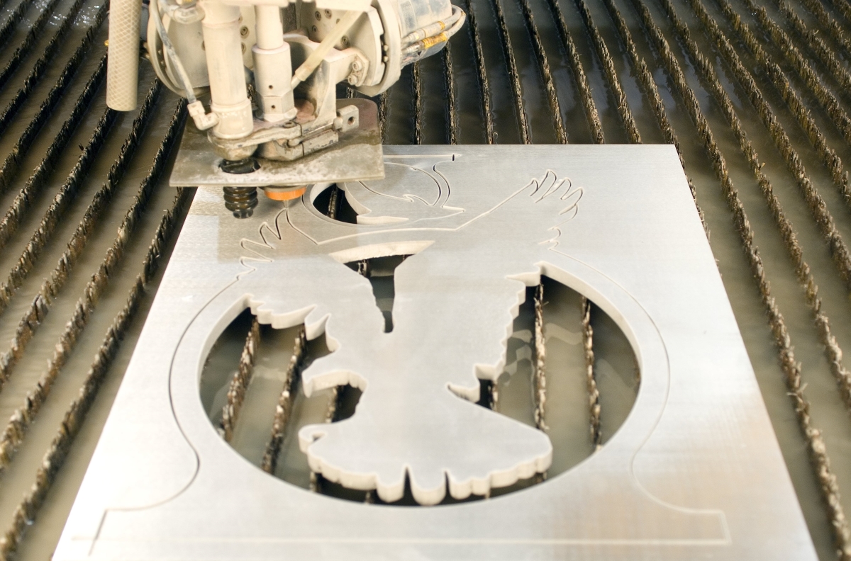
- Aluminum/Steel: Water jets cut well but leave a rough edge (Ra 125–250 μin) and heat-affected zone (HAZ) is minimal, but no dimensional precision for tight-tolerance features.
- ABS/Nylon: Pure water jets (no abrasive) can cut these plastics, but they melt or deform due to water pressure—not suitable for precision parts.
🔍 Key Takeaway: Water jet is for rough cutting thick materials (e.g., 1″ aluminum plate), not precision machining. For tight-tolerance parts, use CNC milling/turning.
✅ Correct Technical Specs: CNC Milling & Turning for Tight Tolerances
(Focus: Aluminum, Steel, ABS, Nylon)
At Honyo Prototype, we achieve ±0.001″ (±0.025mm) tolerances for critical features using high-precision CNC machines (e.g., 5-axis machining centers, Swiss-style lathes). Below are industry-standard specs for each material:
📏 General Tight-Tolerance Requirements
| Parameter | Spec | Notes |
|———–|——|——-|
| Dimensional Tolerance | ±0.001″ (±0.025mm) for critical features; ±0.005″ (±0.127mm) for non-critical | Achievable with rigid setups, calibrated tools, and thermal control |
| Surface Finish (Ra) | 16–32 μin (0.4–0.8 μm) | Lapped/polished for optical/precision applications |
| Geometric Tolerances | ±0.0005″ (±0.013mm) for flatness/roundness | Requires GD&T control and CMM verification |
| Machine Type | 5-axis CNC milling (e.g., DMG MORI, Haas), Swiss turning (e.g., Citizen, Tsugami) | For complex 3D geometries with minimal setup changes |
⚙️ Material-Specific Machining Specs
| Material | Cutting Tools | Speeds/Feeds | Critical Considerations | Tolerance Feasibility |
|———-|—————|————–|————————-|————————|
| Aluminum (6061, 7075) | Carbide end mills (4-flute, TiAlN coating) | Milling: 1,500–3,000 SFM, 0.002–0.005″ per tooth feed
Turning: 1,000–2,500 SFM, 0.003–0.008″ rev feed | – High thermal conductivity → use coolant
– Soft material → avoid chatter; use rigid fixturing | ±0.001″ achievable (e.g., aerospace components) |
| Steel (304 SS, 4140, 17-4 PH) | Carbide tools (AlTiN coating), PCD inserts | Milling: 300–800 SFM, 0.001–0.003″ per tooth
Turning: 200–600 SFM, 0.002–0.005″ rev | – Work hardening risk → sharp tools, high feed rates
– Thermal expansion → coolants (minimum quantity lubrication) | ±0.001″ achievable (e.g., medical implants) |
| ABS (Acrylonitrile Butadiene Styrene) | Carbide tools (sharp edge, uncoated) | Milling: 500–1,000 SFM, 0.004–0.008″ per tooth
Turning: 300–800 SFM, 0.005–0.015″ rev | – Low melting point → avoid heat buildup (use air blast, not coolant)
– Chips clog easily → high spindle speeds | ±0.002″ achievable (e.g., prototypes, housings) |
| Nylon (6/6, 6/12) | Carbide tools (sharp, polished edge) | Milling: 400–800 SFM, 0.003–0.007″ per tooth
Turning: 250–600 SFM, 0.004–0.010″ rev | – Hygroscopic → dry material before machining
– Low thermal conductivity → use air cooling, avoid coolant | ±0.002″ achievable (e.g., gears, bushings) |
🔧 Critical Process Controls for Tight Tolerances
- Thermal Management:
- Aluminum/Steel: Use flood coolant to prevent thermal expansion errors.
- Plastics (ABS/Nylon): Air blast only—coolant causes warpage.
- Fixturing:
- Zero-point clamping systems for minimal deflection.
- Vacuum chucks for thin-walled parts.
- Tooling:
- Balancing tools to <1.0 G at max RPM (prevents vibration).
- In-process tool wear monitoring (e.g., acoustic emission sensors).
- Verification:
- CMM (Coordinate Measuring Machine) with 0.0001″ resolution.
- First-article inspection (FAI) per AS9102 for aerospace.
💡 When to Use Water Jet vs. CNC Machining
| Scenario | Water Jet | CNC Milling/Turning |
|———-|———–|———————|
| Cutting thick metal plates | ✅ Excellent (up to 6″+ thick) | ❌ Not practical |
| Precision holes/slots in aluminum | ❌ ±0.020″ tolerance, tapered edges | ✅ ±0.001″ tolerance, sharp edges |
| 2D plastic parts (ABS/Nylon) | ❌ Melts/deforms material | ✅ Clean cuts with tight tolerances |
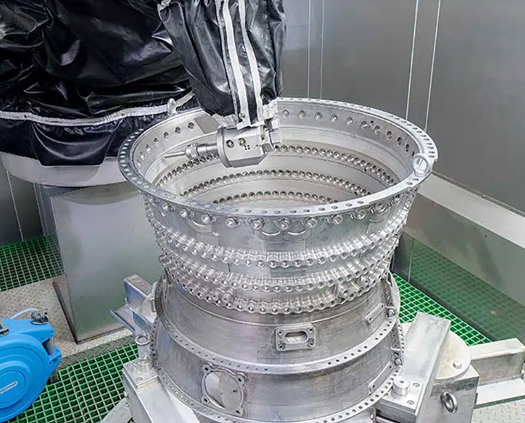
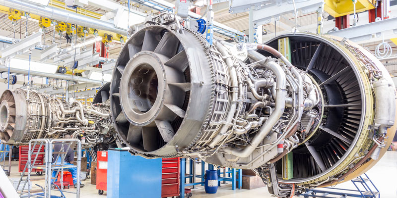
| 3D complex geometries (e.g., turbine blades) | ❌ Only 2D cuts | ✅ 5-axis machining required |
🚨 Final Recommendation
If your project requires tight tolerances (±0.001″) or multi-axis capabilities, water jet cutting is not an option. Instead:
1. For aluminum/steel: Use 5-axis CNC milling (e.g., for aerospace or medical parts).
2. For ABS/Nylon: Use high-speed CNC milling (with air cooling) for prototypes or end-use parts.
At Honyo Prototype, we specialize in CNC machining for tight-tolerance applications—we’d be happy to share a detailed process plan for your specific part. If you meant to ask about water jet specs (for non-precision cutting), I can provide those separately—but they won’t meet your “tight tolerance” or “multi-axis” requirements.
Let me know how you’d like to proceed! 😊
From CAD to Part: The Process
Honyo Prototype – Water-Jet Cutting of Aluminum
End-to-end workflow (CAD → Delivery)
-
Upload CAD
• Acceptable formats: STEP, IGES, XT, SLDPRT, 3DM, STL, DXF/DWG.
• Cloud portal auto-checks file integrity, sheet size vs. stock, and flags non-perpendicular walls that would require 5-axis.
• Instant feedback: “Water-jet only; no post-machining assumed unless noted.” -
AI Quote (≤30 s)
• Neural-net reads 2D/3D geometry, extracts perimeter length, number of pierces, tightest radius, and nesting yield on standard 1.2 m × 2.4 m 6061-T6 sheets.
• Real-time aluminum surcharge from LME + Honyo inventory.
• Outputs: piece price, 3-day vs. 7-day lead-time, break-even quantity, and CO₂ footprint.
• One-click to accept or “Add threading, tapping, anodize” (moves part to hybrid routing). -
DFM (same day)
a. Nest & kerf compensation: 0.76 mm abrasive-jet kerf offset applied; common-line cutting enabled for >3 mm wall spacing.
b. Micro-tab placement: 0.3 mm bridges keep slugs captive, eliminate tab-removal labor.
c. Pierce reduction: start holes moved to scrap regions or shared starts for internal slots.
d. Edge-quality map:
– Q1 (loose tolerance ±0.25 mm) 550 mm/min
– Q3 (precision ±0.08 mm) 200 mm/min
– Q5 (near-machined ±0.05 mm) 120 mm/min + trim pass.
e. Grain direction & flatness call-out noted for downstream brake-form if needed.
f. PDF report returned to customer for e-sign; any change highlights in red. -
Production (1–3 days)
- Sheet prep: 6061-T6 brushed, de-burred, and vacuum-leveled to ≤0.2 mm bow.
- Abrasive: 80-garnet, 60 mesh for thick (>12 mm) cuts; 120 mesh for thin (<3 mm) to reduce taper.
- Machine setup:
– 60 kPsi OMAX 80X dual-head, 2.5 m × 6 m envelope.
– Zero-point fixture clamps outside the nest; saves 15 mm border vs. traditional slats. - Cut sequence: outer perimeter last to maintain thermal stability; 3 mm lift-off distance on pierce.
- In-process CCD camera measures actual kerf width every 500 mm; adaptive feed-rate keeps tolerance band.
- Post-cut:
– 400 bar water rinse to remove garnet embedment.
– Vibratory tumble 15 min for edge-rounding (Ra ≤1.6 µm) when Q3/Q5 specified. -
FAI: laser-scan one part per nest vs. CAD; Cpk ≥1.33 required before batch release.
-
Delivery (next-day)
• Parts ultrasonically dried, LDPE film-masked, then foam-separated in export-grade carton.
• Certificate of Compliance: alloy grade, temper, lot number, water-jet parameters, edge-quality class, and RoHS statement.
• Tracking link auto-emailed; 90 % of EU/US customers receive within 48 h of ship.
Key aluminum-specific notes
• No HAZ: water-jet keeps temper intact—critical for 6061-T6 structural parts.
• Max thickness routinely 150 mm; above 100 mm taper held ≤0.05 mm/mm by tilting head 2–4°.
• Nesting yield on 4 × 8 ft sheet typically 85 % vs. 70 % on laser because kerf is wider but parts can share lines.
Start Your Project
Precision Water Jet Cutting for Aluminum – Fast, Clean, and Zero Heat-Affected Zones
Get flawless cuts for complex geometries and tight tolerances with Honyo Prototype’s state-of-the-art water jet technology. Based in Shenzhen, China, we deliver rapid turnaround and unmatched quality for your aluminum parts.
Contact Susan Leo today for a free quote:
📧 [email protected]
📍 Shenzhen Factory | Global Expertise | ISO-Certified Processes
Ready to elevate your project? Email us now with your specifications!
🚀 Rapid Prototyping Estimator