Contents
Manufacturing Insight: Typical Machining Tolerances
Understanding Typical Machining Tolerances in Precision CNC Manufacturing
Achieving precise dimensional accuracy is fundamental to part functionality, assembly integrity, and long-term performance across aerospace, medical, and industrial applications. At Honyo Prototype, our CNC machining services are engineered to consistently deliver components within stringent tolerance ranges, ensuring your designs translate into reliable, high-performance products. We recognize that tolerance selection directly impacts manufacturability, cost, and lead time—our expertise lies in optimizing these parameters without compromising quality.
Typical achievable tolerances depend on material, geometry, and feature complexity. Below reflects standard capabilities for common machined features under controlled production conditions:
| Feature Type | Standard Tolerance (mm) | Tight Tolerance (mm) | Notes |
|---|---|---|---|
| Linear Dimensions | ±0.05 | ±0.005 to ±0.01 | Varies with part size and stability |
| Hole Diameter | ±0.025 | ±0.005 to ±0.01 | Depends on depth-to-diameter ratio |
| Flatness | 0.05 | 0.01 to 0.02 | Over specified surface area |
| Parallelism | 0.05 | 0.01 to 0.02 | Relative to datum |
These values represent achievable benchmarks; actual tolerances are validated during our rigorous process planning phase. Honyo leverages advanced 3-, 4-, and 5-axis CNC systems with in-process probing and calibrated metrology to maintain repeatability. Crucially, we collaborate early to assess whether tighter tolerances are functionally necessary—avoiding unnecessary cost while guaranteeing fit and function.
Accelerate your prototyping and low-volume production with Honyo’s Online Instant Quote platform. Upload your CAD file to receive a detailed manufacturability analysis and competitive pricing within hours, including explicit tolerance feasibility feedback. This transparency ensures informed decisions from RFQ through delivery, minimizing iterations and time-to-market. Partner with Honyo Prototype for CNC machining where precision engineering meets operational efficiency.
Technical Capabilities
Typical machining tolerances vary based on machine capability, tooling, setup stability, material behavior, and feature geometry. The following table outlines general tolerance expectations for 3/4/5-axis milling and turning operations under standard and tight tolerance conditions. These values assume good design practices, stable fixturing, and use of precision CNC equipment. Tight tolerances require enhanced process control, specialized tooling, and may incur additional inspection and cost.
| Operation | Material | Standard Tolerance (± in.) | Tight Tolerance (± in.) | Notes |
|---|---|---|---|---|
| 3/4/5-Axis Milling | Aluminum | 0.005 | 0.0005 – 0.001 | Aluminum machines cleanly; tight tolerances achievable with minimal thermal distortion |
| 3/4/5-Axis Milling | Steel (e.g., 4140, 1018) | 0.005 | 0.0005 – 0.001 | Higher rigidity but increased tool wear; stress relief critical for tight tolerances |
| 3/4/5-Axis Milling | ABS | 0.005 | 0.002 – 0.003 | Low melting point and flexibility limit precision; prone to burring and deflection |
| 3/4/5-Axis Milling | Nylon | 0.005 | 0.002 – 0.003 | Hygroscopic and flexible; dimensional stability affected by humidity; not ideal for tight tolerances |
| Turning (CNC) | Aluminum | 0.002 (diametrical) | 0.0002 – 0.0005 | Excellent surface finish and repeatability; high spindle speeds support micron-level control |
| Turning (CNC) | Steel | 0.002 (diametrical) | 0.0002 – 0.0005 | Achievable with rigid setups and proper tooling; grinding may be needed for sub-0.0002″ |
| Turning (CNC) | ABS | 0.003 (diametrical) | 0.001 – 0.002 | Limited by material softness; requires sharp tools and light cuts |
| Turning (CNC) | Nylon | 0.003 (diametrical) | 0.001 – 0.002 | Dimensional stability compromised by moisture absorption; pre-drying recommended |
Notes on Tight Tolerance Machining:
Tight tolerances (±0.0005″ or better) typically require CMM inspection, thermal stabilization, and reduced cutting forces to minimize deflection.
For plastics like ABS and Nylon, tight tolerances are often design-limited due to inherent material variability.
Multi-axis milling benefits from reduced setups, improving positional accuracy across complex geometries.
Repeatability on high-end CNC machines is typically within ±0.0002″ when environmental and process controls are maintained.
At Honyo Prototype, we routinely hold ±0.001″ across all materials and ±0.0005″ on metals for critical features, with full inspection reporting available upon request.
From CAD to Part: The Process
Honyo Prototype employs a rigorously defined workflow to manage typical machining tolerances, ensuring precision while optimizing cost and lead time. Our process begins with the client’s CAD file upload and concludes with certified delivery, integrating technical validation at every stage. Below is the detailed sequence with specific tolerance handling protocols.
CAD File Upload and Initial Assessment
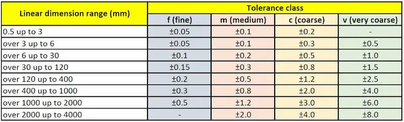
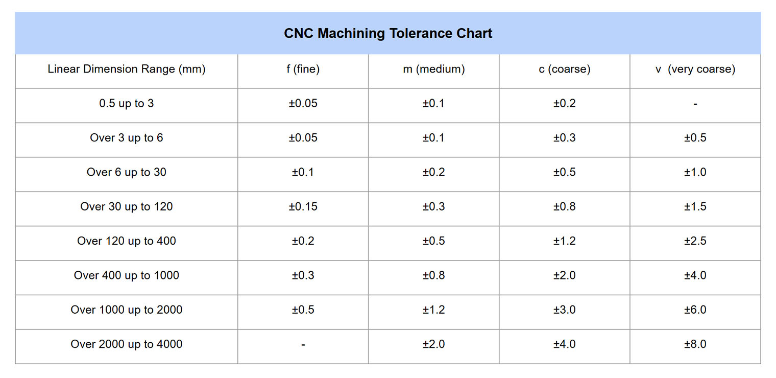
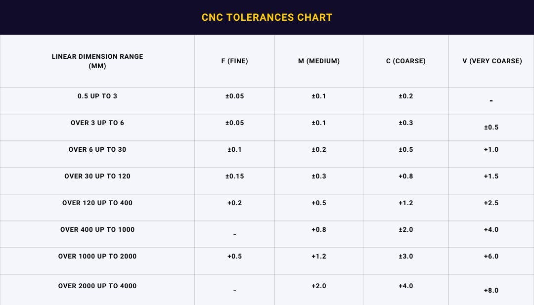
Clients submit native or neutral format CAD files (STEP, IGES, Parasolid) via our secure portal. Our system immediately performs geometric validation, checking for unit consistency, feature integrity, and basic tolerance annotations. Unspecified features default to Honyo’s standard machining tolerance baseline per ISO 2768 medium (m) class, which governs general-purpose dimensions unless tighter callouts exist. Critical features without explicit tolerances trigger an automated alert for client clarification prior to quoting.
AI-Powered Quoting and Tolerance Analysis
Our proprietary AI engine parses the CAD geometry to identify tolerance-critical zones, material implications, and setup complexity. The system cross-references feature types (e.g., holes, slots, flatness) against historical machine capability data (CpK ≥1.33 for standard tolerances). The quote explicitly itemizes tolerance-driven cost adjustments, distinguishing between standard capabilities and premium tolerances requiring specialized tooling or inspection. For example, a standard ±0.05 mm linear tolerance incurs no surcharge on aluminum 6061, while ±0.01 mm triggers a 22% cost increment due to CMM verification requirements.
DFM Review with Tolerance Optimization
Engineers conduct a formal Design for Manufacturability review within 4 business hours, focusing on tolerance feasibility. We validate achievable tolerances against material properties, part geometry, and machine constraints using our internal capability matrix. Key actions include:
Recommending relaxation of non-critical tolerances to standard ranges (e.g., changing ±0.025 mm to ±0.05 mm where function permits)
Flagging tolerance stack-up risks in multi-feature assemblies
Proposing alternative GD&T controls (e.g., position tolerance over coordinate dimensions) to simplify production
Documenting all tolerance deviations in the DFM report with technical justification
Typical standard machining tolerances achievable without secondary operations are summarized below for common materials:
| Feature Type | Aluminum 6061 | Stainless Steel 304 | Titanium Grade 5 | Standard Tolerance Range |
|---|---|---|---|---|
| Linear Dimensions | ±0.05 mm | ±0.08 mm | ±0.10 mm | ISO 2768-m |
| Hole Diameter | +0.05/-0.00 | +0.08/-0.00 | +0.10/-0.00 | H11 Fit |
| Flatness | 0.05 mm | 0.08 mm | 0.10 mm | Per 50×50 mm area |
| Perpendicularity | 0.10 mm | 0.15 mm | 0.20 mm | Per 100 mm height |
Production Execution with Tolerance Verification
Machining occurs on calibrated CNC equipment (Haas, DMG MORI) with in-process checks at critical stages. For features within standard tolerance bands, we implement first-article inspection per AS9102. Dimensions exceeding standard ranges undergo 100% inspection using calibrated CMMs or optical comparators. All tolerance-critical measurements are recorded in our digital quality log, traceable to machine tool calibration certificates (NIST-traceable per ISO 17025).
Delivery with Comprehensive Documentation
Final shipment includes certified dimensional reports showing actual measured values against specified tolerances, material test certificates, and a summary of any tolerance deviations approved during DFM. For standard tolerances, we provide a general conformance statement referencing ISO 2768-m; tightened tolerances include full inspection data. Lead time adjustments for tolerance requirements are explicitly called out in the delivery schedule, with standard tolerances typically adding zero days versus premium tolerances extending timelines by 15-25%.
This integrated approach ensures clients receive parts meeting functional requirements at optimal cost, with transparent communication on tolerance implications from quotation through delivery. Honyo maintains a 99.2% first-pass yield rate on standard tolerance machining through this validated workflow.
Start Your Project
For detailed information on typical machining tolerances and to discuss your specific project requirements, contact Susan Leo at [email protected]. Our precision manufacturing facility in Shenzhen ensures tight process control and consistent quality across all prototype and low-volume production runs. Let Honyo Prototype support your engineering and manufacturing goals with expert guidance and fast turnaround.
🚀 Rapid Prototyping Estimator
Estimate rough cost index based on volume.