Contents
Manufacturing Insight: Tool Offset Cnc
Precision Through Precision Engineering: Mastering Tool Offset in CNC Machining
At Honyo Prototype, we recognize that true precision in CNC machining hinges on meticulous control of variables often overlooked in standard workflows—particularly tool offset management. Tool offset errors, whether from thermal drift, tool wear, or calibration inaccuracies, directly impact dimensional integrity, surface finish, and repeatability. Our advanced CNC machining services integrate proprietary offset calibration protocols and real-time adaptive compensation systems to eliminate these variables, ensuring tolerances as tight as ±0.0002 inches are consistently achieved across complex geometries and demanding materials. This mastery of micro-adjustments translates to reduced scrap rates, accelerated time-to-prototype, and seamless scalability from prototype to production.
Backed by ISO 9001-certified processes and a fleet of multi-axis CNC centers equipped with high-resolution probing and thermal compensation, Honyo delivers uncompromising accuracy for aerospace, medical, and industrial clients. Every component undergoes rigorous in-process verification, where tool offset parameters are dynamically validated against CAD models to preempt deviations before they occur. The result is first-article success rates exceeding 98%—minimizing costly iterations and accelerating your product development cycle.
Experience the Honyo advantage with our Online Instant Quote platform. Upload your CAD file, specify critical tolerances including tool offset-sensitive features, and receive a detailed machining assessment with lead time and cost within minutes. Precision engineering starts with a single click.
Technical Capabilities
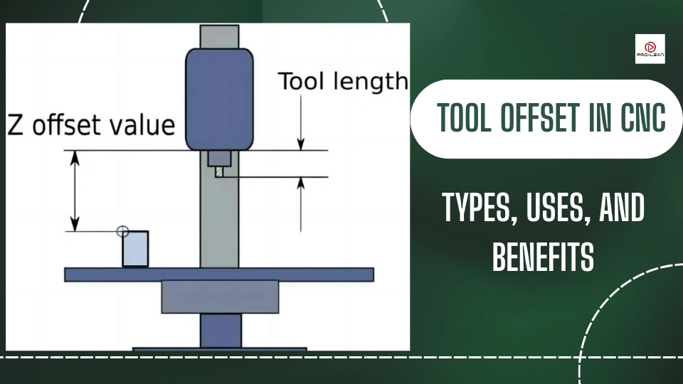
Tool offset in CNC machining refers to the programmed adjustment that accounts for the physical dimensions of cutting tools relative to the machine spindle or a reference tool. Accurate tool offset setup is critical in 3-axis, 4-axis, and 5-axis milling as well as turning operations—especially when holding tight tolerances (±0.0005″ or ±0.01 mm). Proper offset values ensure dimensional accuracy, surface finish integrity, and repeatability across multiple setups and tool changes.
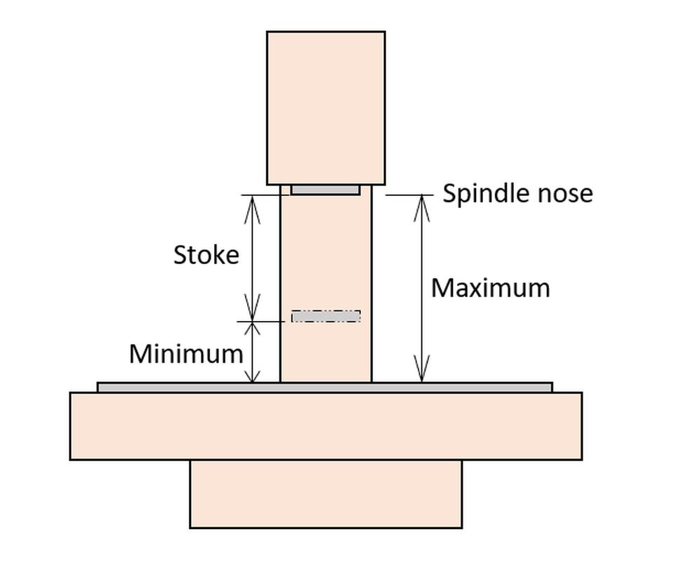
In multi-axis milling, tool offsets include both length (Z-axis) and radius (X/Y-axis) compensation, with additional vector-based tool center point control in 4-axis and 5-axis configurations. For turning operations, tool nose radius compensation (TNRC) and tool tip orientation are factored into the offset data. These values are stored in the CNC control (e.g., Fanuc, Siemens Sinumerik, Heidenhain) and applied during toolpath interpolation.
The following table outlines typical tool offset considerations based on machining process, material, and tolerance requirements:
| Parameter | 3-Axis Milling | 4-Axis Milling | 5-Axis Milling | CNC Turning | Notes |
|---|---|---|---|---|---|
| Tool Length Offset (TLO) | Critical (±0.001 mm measurement repeatability) | Critical (automated probing common) | Essential (dynamic tilt/rotary compensation) | Moderate (consistent tool holder) | Measured via touch-off or laser probe |
| Tool Radius Offset | Required for end mills (±0.002 mm adjustment) | Required with angular approach | Advanced 3D radius compensation | N/A (replaced by TNRC) | Adjusted for wear in high-precision work |
| Tool Nose Radius Compensation (TNRC) | Not applicable | Not applicable | Not applicable | Required (R0.4–R1.2 typical) | Critical for profile accuracy in steel/Al |
| Probe-Based Calibration | Common for setup | Standard (rotary centering) | Mandatory (RTCP/TCPC enabled) | Used for tool presetting | Ensures sub-micron offset accuracy |
| Typical Tolerance Range | ±0.0005″ (±0.013 mm) | ±0.0004″ (±0.010 mm) | ±0.0002″ (±0.005 mm) | ±0.0005″ (±0.013 mm) | Depends on machine rigidity and control |
| Material-Specific Tool Wear Offset Adjustment | Aluminum: Low wear – minimal adjustment Steel: High wear – frequent offset updates ABS: Low wear – stable offsets Nylon: Minimal wear but chip adhesion risk |
Same as 3-axis with angular exposure effects | Higher thermal drift in steel; monitor flank wear | Aluminum: Sharp inserts, small nose rad Steel: Coated carbide, larger nose rad ABS/Nylon: Positive rake, polished flank |
Adjust offsets based on material machinability |
| Common Offset Storage Method | Tool table (H/D codes) | Indexed tool table with rotary vectors | Full 5-axis tool data (length, radius, orientation) | Tool geometry + wear tables (T-codes) | Integrated with tool presetters and CAM systems |
For tight-tolerance work in materials such as aluminum and steel, in-process probing is recommended to verify and update tool offsets dynamically. In non-metallic materials like ABS and nylon, lower cutting forces reduce tool deflection, but thermal expansion and chip evacuation must be monitored to maintain offset integrity. In 5-axis milling, tool offsets are often managed through Tool Center Point Control (TCPC) or Rotational Tool Center Point (RTCP), allowing the CNC to automatically compensate for tool geometry during simultaneous multi-axis motion.
From CAD to Part: The Process
Honyo Prototype executes precision CNC machining through a rigorously defined workflow where tool offset management is integrated into critical stages, not treated as a standalone process. Tool offsets—comprising tool length, diameter, and wear compensation—are systematically applied during CNC programming and machine operation to ensure dimensional accuracy. Below is the accurate sequence with explicit integration points for tool offset strategy:
CAD Upload and AI Quoting
Clients submit native or neutral CAD formats (STEP, IGES, Parasolid). Our AI quoting engine extracts geometric complexity, material requirements, and tolerance stack-ups. While tool offsets are not calculated here, the AI identifies features demanding tight tolerances (e.g., ±0.005 mm pockets or bores), triggering downstream flags for specialized offset protocols in DFM.
DFM Analysis and Offset Strategy Development
Our engineering team conducts a formal Design for Manufacturability review. This phase determines tool offset methodology:
Tool length offsets are assigned per刀具 based on machine-specific reference points
Diameter offsets are calculated for contouring operations using cutter compensation (G41/G42)
Wear offsets are pre-planned for high-volume runs using predictive tool-life models
Critical tolerance zones undergo virtual offset simulation to prevent overcut/undercut scenarios. Clients receive actionable feedback if geometry conflicts with offset-driven machining (e.g., thin walls prone to deflection).
Production: Offset Implementation and Verification
Tool offsets are dynamically managed during production:
1. Pre-machine setup: Laser tool setters measure actual tool dimensions; values populate CNC offset registers
2. In-process: On-machine probing validates critical features, auto-updating wear offsets via M-code calls
3. Mid-run: Statistical process control (SPC) tracks offset drift; adjustments occur if Cpk falls below 1.33
Tool Offset Types and Control Methods
| Offset Type | Application Trigger | Adjustment Method | Verification Frequency |
|——————-|——————————|—————————————|————————|
| Tool Length | All Z-axis operations | Laser measurement pre-run | Per setup |
| Diameter | Profile milling, contouring | CNC cutter comp + in-probe validation | Every 50 parts |
| Wear Compensation | High-volume production runs | SPC-driven auto-updates via MTConnect | Per SPC control chart |
Delivery and Documentation
Final inspection includes offset traceability:
CMM reports correlate measured dimensions to applied offset values
Machine logs documenting offset adjustments are archived in the digital twin
Certificates of Conformance specify offset management protocols used
All deliverables include as-machined data showing how offset strategies maintained tolerances per AS9100 Rev D standards. This closed-loop approach ensures dimensional repeatability while minimizing scrap—critical for aerospace and medical clients requiring ±0.0025 mm consistency. Tool offset integrity is validated before shipment, not treated as a separate workflow phase.
Start Your Project
For precise tool offset CNC solutions tailored to your manufacturing requirements, contact Susan Leo at [email protected]. With our advanced machining capabilities and quality control processes in place at our Shenzhen-based factory, Honyo Prototype ensures consistent accuracy and fast turnaround for your prototyping and production needs. Reach out today to optimize your CNC operations with expert support and engineering precision.
🚀 Rapid Prototyping Estimator
Estimate rough cost index based on volume.