Contents
Manufacturing Insight: Surface Finish Scale For Machining
Understanding Surface Finish Requirements in Precision CNC Machining
Achieving the correct surface finish is a critical factor in functional part performance, directly influencing wear resistance, fatigue strength, sealing capabilities, and assembly precision. At Honyo Prototype, our advanced CNC machining services—encompassing multi-axis milling, turning, and micro-machining—are engineered to consistently deliver surface finishes ranging from coarse industrial textures (Ra 12.5 µm) to mirror-like optical grades (Ra 0.05 µm), aligned with ISO 1302 and ASME B46.1 standards. We recognize that ambiguous finish specifications often lead to costly rework or part rejection; therefore, our engineering team collaborates closely with clients to define exact requirements within the context of material properties, geometry, and end-use application.
Our process leverages high-stability machine platforms, optimized toolpath strategies, and stringent in-process metrology to ensure finish repeatability across prototypes and low-volume production runs. To streamline your sourcing workflow, Honyo provides an Online Instant Quote platform where you can upload CAD files, specify surface finish parameters via standardized scales, and receive detailed manufacturability feedback alongside pricing within hours—not days. Eliminate guesswork in finish specification and accelerate time-to-part with Honyo’s integrated engineering and quoting expertise. Optimize your next project by defining precision upfront.
Technical Capabilities
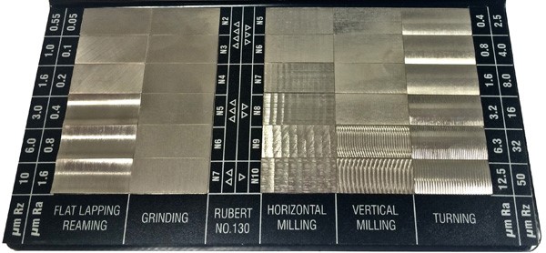
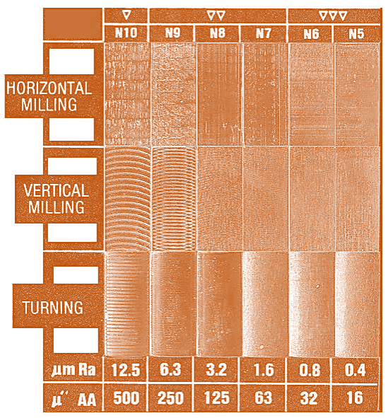
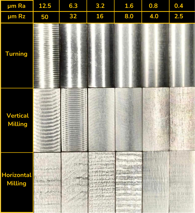
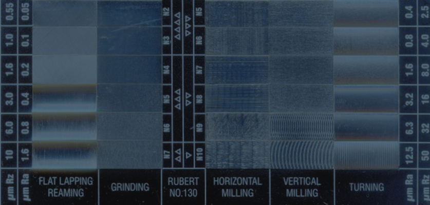
Surface Finish Scale for Machining
The surface finish scale in precision machining quantifies the texture or roughness of a machined surface, typically expressed in microinches (µin) or micrometers (µm). It is critical in applications requiring tight tolerances, functional performance, and aesthetic quality, especially in 3/4/5-axis milling and turning operations. Surface finish requirements vary based on material properties, tool selection, cutting parameters, and part function.
Below is a technical reference table outlining typical surface finish ranges achievable in 3/4/5-axis milling and turning for common engineering materials, under tight tolerance conditions (±0.0005″ to ±0.005″) and optimal machining practices.
| Material | Process | Typical Surface Finish (Ra, µin) | Typical Surface Finish (Ra, µm) | Notes |
|---|---|---|---|---|
| Aluminum (6061, 7075) | 3/4/5-Axis Milling | 16–32 µin | 0.4–0.8 µm | High-speed cutting with sharp carbide tools yields excellent finishes; easily polished to <8 µin for cosmetic parts |
| Aluminum (6061, 7075) | Turning | 16–64 µin | 0.4–1.6 µm | Achieves fine finishes with proper tool nose radius and low feed rates; ideal for shafts and housings |
| Steel (4140, 1018) | 3/4/5-Axis Milling | 32–64 µin | 0.8–1.6 µm | Harder material requires rigid setups and coated inserts; can achieve 16 µin with finish passes and climb milling |
| Steel (4140, 1018) | Turning | 16–32 µin | 0.4–0.8 µm | Excellent repeatability with CNC turning; tight tolerances maintained with consistent tool wear monitoring |
| ABS (Thermoplastic) | 3/4/5-Axis Milling | 64–125 µin | 1.6–3.2 µm | Prone to melting and burring; requires sharp tools, high RPM, and low feed; post-processing often needed |
| ABS (Thermoplastic) | Turning | 64–250 µin | 1.6–6.3 µm | Limited use in turning due to low strength and thermal sensitivity; surface quality varies significantly with cutting speed |
| Nylon (PA6, PA66) | 3/4/5-Axis Milling | 64–125 µin | 1.6–3.2 µm | Exhibits “gummy” behavior; needs sharp, polished tools and cool running parameters; slight dimensional variability due to hygroscopy |
| Nylon (PA6, PA66) | Turning | 64–200 µin | 1.6–5.0 µm | Dimensional stability challenging; requires dry material and controlled environment for tight tolerance work |
Additional Technical Considerations:
Surface finish is influenced by multiple factors including tool geometry (nose radius, rake angle), spindle stability, tool path strategy (stepover, direction), coolant application, and workholding rigidity. In multi-axis milling, tool engagement and consistent tool orientation help maintain uniform surface texture across complex geometries.
For tight tolerance components, surface finish directly affects fit, wear resistance, and sealing performance. Finishes tighter than 16 µin (0.4 µm) often require grinding, honing, or polishing and are not typically achieved through conventional CNC machining alone.
Material-specific behaviors:
Aluminum allows for the best surface finishes due to its machinability and low work-hardening tendency.
Steels require more robust tooling and slower parameters but can achieve high precision and repeatable surface quality.
ABS and Nylon, as thermoplastics, present challenges due to low thermal conductivity and elastic recovery, often resulting in less consistent finishes compared to metals.
For critical applications, surface finish is verified using profilometers and specified using ISO or ASME standards (e.g., ASME Y14.36M, ISO 1302).
From CAD to Part: The Process
Honyo Prototype Surface Finish Scale Integration Process
Honyo Prototype integrates surface finish specifications systematically across our end-to-end workflow to ensure machined components meet precise aesthetic and functional requirements. This process begins at CAD submission and concludes with verified delivery, with critical checkpoints at each stage to prevent misinterpretation or deviation. Below is the detailed execution for surface finish management within our standard flow.
CAD File Submission and Annotation Review
Upon CAD upload, our system performs an initial scan for surface finish annotations per ISO 1302 or ASME Y14.36M standards. Critical areas requiring specific roughness averages (Ra) or peak count parameters are isolated. If annotations are missing, ambiguous, or conflict with geometric tolerances, the file triggers an automated hold for engineering review. We prioritize explicit Ra values over generic descriptors (e.g., “smooth finish”) to avoid production ambiguity.
AI-Powered Quoting with Finish Validation
Our AI quoting engine cross-references annotated surface finishes against Honyo’s machine capability database. For example, an Ra 0.8 µm callout on aluminum is validated against our 5-axis milling center’s achievable range (typically Ra 0.4–3.2 µm for milled surfaces). The quote explicitly lists:
Feasibility confirmation for each specified finish
Cost impact of non-standard finishes (e.g., Ra 0.2 µm requiring diamond turning)
Recommended alternatives if requested finishes exceed capabilities (e.g., suggesting bead blasting instead of mirror polishing for cost-sensitive parts)
Unrealistic specifications (e.g., Ra 0.1 µm on large flat surfaces via conventional milling) are flagged with technical justification before quote finalization.
DFM Analysis for Surface Finish Optimization
During Design for Manufacturability (DFM), our engineers conduct a dedicated surface finish review:
Material compatibility (e.g., stainless steel achieving Ra 0.4 µm vs. cast aluminum at Ra 1.6 µm with identical toolpaths)
Tooling constraints (e.g., minimum cavity radius limiting achievable finish in pockets)
Cross-contamination risks (e.g., segregating parts requiring Ra 0.2 µm from standard Ra 3.2 µm batches)
We provide actionable feedback via the DFM report, including GD&T adjustments to maintain functionality while easing finish requirements. For critical applications, we propose sample runs to validate finish attainment pre-production.
Production Execution and In-Process Verification
Surface finish specifications drive machine parameter selection:
Tool geometry, feed rates, and spindle speeds are optimized for target Ra
Dedicated toolpaths for critical surfaces (e.g., slow finishing passes with polished inserts)
In-process profilometer checks at 25% and 75% production milestones
All finish-critical parts undergo 100% inspection using calibrated surface roughness testers (e.g., Mitutoyo SJ-410). Data is logged against part serial numbers for traceability.
Delivery Documentation and Certification
Final delivery includes:
Dimensional report with surface finish verification at all annotated locations
Raw profilometer data plots showing Ra, Rz, and Rmax values
Material certification confirming post-machining treatments (e.g., passivation for stainless steel)
For aerospace or medical clients, we supply full AS9102 or ISO 13485-compliant documentation packages with finish validation.
Surface Finish Capability Reference
Standard achievable ranges for common processes at Honyo:
| Process | Material Group | Typical Ra Range (µm) | Max Achievable Ra (µm) | Key Limitations |
|---|---|---|---|---|
| CNC Milling | Metals | 0.4–6.3 | 0.2 (with diamond tools) | Deep cavities >10:1 aspect ratio |
| CNC Turning | Plastics | 0.8–12.5 | 0.4 | Thin-walled sections prone to chatter |
| Grinding | Hardened Steel | 0.1–0.8 | 0.05 | Flatness distortion risk >150mm |
| As-Machined (No Spec) | All | 3.2–12.5 | N/A | Visible tool marks acceptable |
This integrated approach ensures surface finish requirements are technically validated, cost-optimized, and rigorously controlled from design intent to certified delivery. We eliminate finish-related rework through proactive collaboration at every phase, maintaining >99.2% first-pass yield on finish-critical components.
Start Your Project
Explore our comprehensive surface finish scale for machining to achieve precise, repeatable results in your prototyping and production workflows. From Ra values to visual finish standards, we ensure dimensional accuracy and aesthetic consistency across all machined components.
For technical specifications or custom finish requirements, contact Susan Leo at [email protected]. Our manufacturing facility is based in Shenzhen, enabling fast turnaround and strict quality control for both low-volume prototypes and high-volume production runs.
🚀 Rapid Prototyping Estimator
Estimate rough cost index based on volume.