Contents
Manufacturing Insight: Sheet Metal Tolerances Thickness
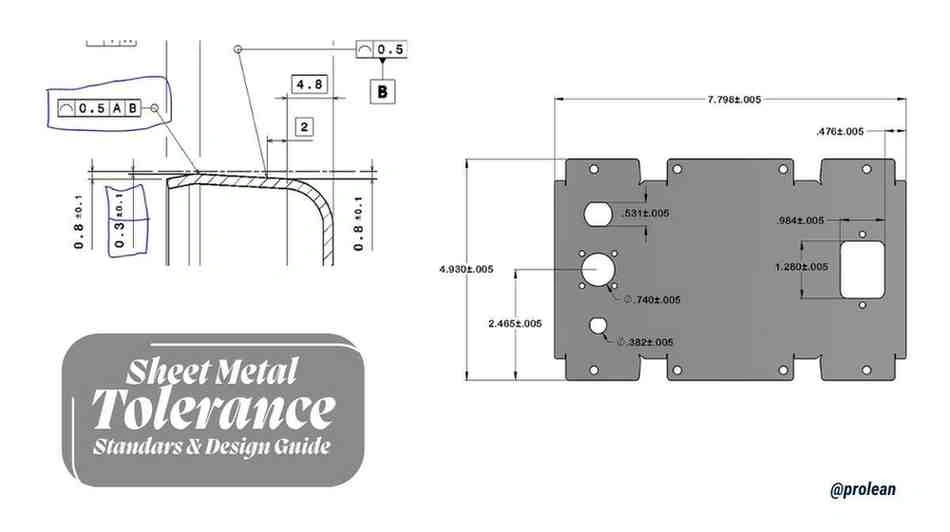
Sheet Metal Tolerance Precision: Ensuring Dimensional Integrity in Your Prototypes and Production Runs
Achieving precise sheet metal thickness tolerances is fundamental to the structural integrity, fit, and functionality of fabricated components. Variations beyond specified limits can compromise assembly, performance, and end-product reliability, particularly in high-precision industries like aerospace, medical devices, and electronics. At Honyo Prototype, we recognize that consistent thickness control—alongside critical bend radii, hole placement, and flatness—is non-negotiable for mission-critical applications. Our advanced sheet metal fabrication capabilities integrate state-of-the-art laser cutting, CNC punching, precision bending, and rigorous in-process inspection to maintain tolerances as tight as ±0.05 mm on thickness and geometric features.
We leverage decades of metallurgical expertise to select optimal materials—from stainless steel and aluminum alloys to specialized composites—ensuring dimensional stability throughout forming and finishing processes. Every project undergoes stringent first-article inspection (FAI) and statistical process control (SPC) to validate conformance to your engineering drawings and industry standards (e.g., ISO 2768, GD&T). This commitment eliminates costly rework and accelerates time-to-market for your most demanding designs.
Streamline your procurement with Honyo’s Online Instant Quote platform. Upload your STEP or DXF files to receive a detailed, transparent cost and lead-time estimate within minutes—valid for both rapid prototyping and low-to-mid volume production. Experience how our tolerance-driven manufacturing process delivers parts that meet exact specifications, every time. Start your quote today and partner with a fabricator built for precision.
Technical Capabilities
Sheet metal tolerances for thickness are critical in manufacturing processes such as laser cutting, bending, and welding. These tolerances ensure dimensional accuracy, part fit, and structural integrity. While nominal material thickness is specified during design, actual thickness can vary based on manufacturing standards and material type. The following table outlines typical thickness tolerances and process-specific considerations for common materials used at Honyo Prototype: Aluminum, Steel, ABS, and Nylon.
| Material | Nominal Thickness Range (mm) | Thickness Tolerance (mm) | Laser Cutting Suitability | Bending Considerations | Welding Compatibility | Notes |
|---|---|---|---|---|---|---|
| Aluminum (e.g., 5052, 6061) | 0.5 – 6.0 | ±0.10 to ±0.15 | Excellent – clean cuts, minimal dross | Requires larger bend radii; springback must be compensated | Weldable with proper techniques (TIG/MIG); avoid warpage | Common in lightweight structural applications |
| Cold Rolled Steel (CRS) | 0.5 – 10.0 | ±0.08 to ±0.13 | Excellent – high precision, fast processing | Standard bend allowances apply; sharp bends possible with tooling | Highly weldable (MIG/TIG/Spot); post-weld finishing often needed | Preferred for high-strength enclosures and brackets |
| ABS (Acrylonitrile Butadiene Styrene) | 1.0 – 5.0 | ±0.20 to ±0.30 | Limited – possible with CO₂ lasers; risk of melting | Poor – not recommended for sheet metal-style bending | Not weldable in traditional sense; solvent bonding or adhesives used | Thermoplastic; used for non-structural, prototyping, or enclosures |
| Nylon (Polyamide) | 1.0 – 6.0 | ±0.20 to ±0.35 | Poor – high reflectivity and melting risk | Not suitable for metal-style air bending; formable via heating | Not weldable with standard methods; friction or ultrasonic welding possible | High wear resistance; used in insulating or low-friction components |
Process Notes:
Laser Cutting:
Tolerances are influenced by beam focus, assist gas, and material reflectivity. Metals like aluminum and steel achieve tight kerf widths (typically 0.1–0.3 mm), while plastics like ABS and nylon require careful parameter control to avoid thermal damage.
Bending:
Minimum bend radius is typically 1x material thickness for steel and aluminum. ABS and nylon do not behave predictably under standard V-die bending and are generally not processed using sheet metal brake forms.
Welding:
Only conductive materials (aluminum, steel) are compatible with arc or resistance welding. Plastics require alternative joining methods and are excluded from traditional sheet metal welding workflows.
For precision sheet metal fabrication at Honyo Prototype, aluminum and steel remain the primary materials due to their compatibility with laser cutting, bending, and welding processes, as well as tighter thickness control. ABS and nylon are included for design comparison but are not standard in metalworking contexts.
From CAD to Part: The Process
Honyo Prototype implements a rigorous, standards-driven workflow for managing sheet metal thickness tolerances throughout the manufacturing lifecycle. Our process ensures dimensional accuracy while optimizing for production feasibility and cost efficiency. Below is the detailed technical sequence for sheet metal thickness tolerance validation and control.
Upon CAD file upload, our AI-powered quoting system immediately parses geometric and material data. The system cross-references the specified material grade (e.g., ASTM A36, EN 10025 S355) against ISO 9013 Class C1 thickness tolerance standards as a baseline. Critical parameters including nominal thickness, material type, and part geometry are extracted for preliminary tolerance assessment. The AI engine flags any thickness specifications outside standard industrial capabilities (e.g., requesting ±0.02mm tolerance on 6mm aluminum) before formal quotation.
During the AI quotation phase, thickness tolerance feasibility is evaluated against three key datasets: supplier-certified material mill certificates, historical machine capability data from our press brakes and lasers, and statistical process control (SPC) records from prior production runs. Tolerances tighter than ISO 9013 Class C1 trigger automatic cost modifiers reflecting required process controls. The quotation explicitly states achievable thickness tolerances based on material grade and thickness range, with deviations from standard tolerances clearly itemized in pricing.
The DFM (Design for Manufacturability) stage involves multi-layered thickness tolerance validation. Our engineering team conducts:
Material thickness verification against supplier mill test reports to confirm incoming stock meets ASTM/EN specifications.
Formability analysis to determine if specified tolerances are maintainable through bending operations (e.g., springback effects on 0.8mm stainless steel).
Process capability simulation using press brake force calculators to ensure thickness consistency across bend radii.
Any tolerance conflicts are resolved through collaborative engineering feedback, with formal deviation approval required for non-standard specifications.
Production executes thickness tolerance control via integrated quality gates:
Incoming material inspection validates thickness using calibrated micrometers at 5+ points per sheet, with data logged against mill certificate lot numbers.
In-process checks during cutting (laser/shear) and forming measure thickness at critical zones using ultrasonic gauges to detect localized thinning.
Final inspection employs CMM or optical comparators for high-tolerance parts, with thickness measurements recorded in the first-article inspection (FAI) report per AS9102 standards.
Delivery includes comprehensive documentation certifying thickness conformance:
Material traceability certificates showing mill test results.
FAI reports with actual thickness measurements at designated critical features.
SPC charts demonstrating process capability (Cp/Cpk ≥1.33 for standard tolerances).
All deliverables reference the applicable standard (typically ISO 9013 Class C1) with explicit notation of any approved deviations.
The following table summarizes our standard thickness tolerance framework based on ISO 9013, with adaptive controls for non-standard requirements:
| Nominal Thickness Range | Standard Tolerance (ISO 9013 Class C1) | Honyo Enhanced Control Threshold | Required Verification Method |
|---|---|---|---|
| 0.5 mm to 1.0 mm | ±0.10 mm | Tighter than ±0.05 mm | Ultrasonic gauge + SPC monitoring |
| 1.0 mm to 3.0 mm | ±0.15 mm | Tighter than ±0.08 mm | Micrometer + FAI at 100% points |
| 3.0 mm to 6.0 mm | ±0.20 mm | Tighter than ±0.12 mm | Calibrated micrometer + batch sampling |
| >6.0 mm | ±0.25 mm | Tighter than ±0.15 mm | Mill certificate validation only |
This structured approach ensures thickness tolerances are validated at every phase while maintaining transparency on achievable specifications. We prioritize adherence to international standards while providing technical flexibility for critical applications through documented engineering controls. All tolerance decisions are traceable to material properties and machine capability data, eliminating subjective interpretation during production.
Start Your Project
For detailed information on sheet metal tolerances and thickness specifications, contact Susan Leo at [email protected]. Our precision manufacturing facility in Shenzhen ensures strict adherence to industry standards, delivering consistent quality for your prototyping and production needs. Reach out today to discuss your project requirements and receive expert technical support.
🚀 Rapid Prototyping Estimator
Estimate rough cost index based on volume.