Contents
Manufacturing Insight: Sheet Metal Fabrication Tools And Equipment
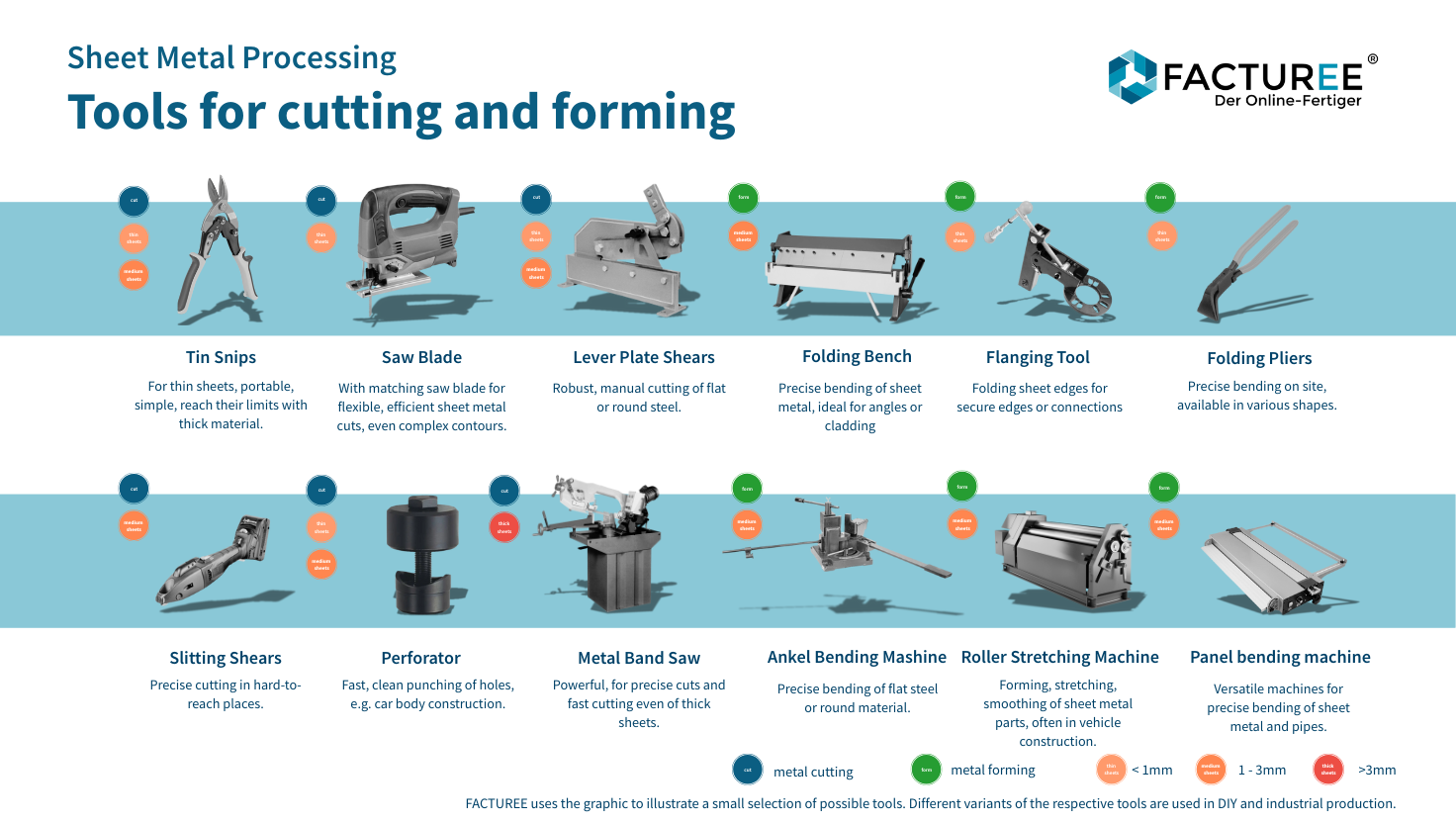
Precision Sheet Metal Fabrication Capabilities at Honyo Prototype
Honyo Prototype delivers advanced sheet metal fabrication services engineered for rapid prototyping and low-volume production, leveraging a comprehensive suite of industry-grade tools and equipment. Our facility integrates high-precision laser cutting systems, CNC turret presses, hydraulic press brakes with automated tool changers, and robotic welding cells to execute complex geometries with tight tolerances down to ±0.005 inches. This technical infrastructure ensures consistent repeatability and material integrity across aluminum, stainless steel, and specialty alloys, directly supporting your product development lifecycle from concept validation to pre-production builds.
We recognize that speed-to-quote significantly impacts your project timelines. To eliminate traditional quoting bottlenecks, Honyo Prototype provides an Online Instant Quote platform where engineers and procurement teams can upload CAD files and receive detailed cost and lead time estimates within minutes—not days. This digital workflow, backed by our in-house manufacturing expertise, allows you to iterate designs faster and accelerate time-to-market without compromising on the rigor of DFM analysis or material selection. Partner with Honyo to transform your sheet metal requirements into precision-engineered components with unmatched efficiency.
Technical Capabilities
Sheet Metal Fabrication Tools and Equipment – Technical Specifications
The following table outlines key technical specifications for major sheet metal fabrication processes—Laser Cutting, Bending, and Welding—with compatibility across common materials including Aluminum, Steel, ABS, and Nylon. These tools are essential in precision prototyping and low-to-medium volume production environments.
| Process | Equipment Type | Power/Force Capacity | Cutting/Bending Thickness Range | Accuracy/Tolerance | Compatible Materials | Additional Notes |
|---|---|---|---|---|---|---|
| Laser Cutting | Fiber Laser Cutting Machine | 1–6 kW laser source | 0.5–25 mm (Steel), 0.5–20 mm (Aluminum) | ±0.1 mm per 100 mm | Aluminum, Steel, ABS (limited), Nylon (not recommended) | Non-metallics like ABS may be cut with CO₂ lasers; fiber lasers are optimized for metals. ABS and Nylon require specialized settings due to melting behavior. |
| Bending | CNC Press Brake | 30–300 tons of bending force | 0.5–12 mm (Steel), 0.5–16 mm (Aluminum) | ±0.2° angular, ±0.1 mm linear | Aluminum, Steel (ABS and Nylon not suitable for bending in sheet form) | Tooling (punch and die) must match material thickness and bend radius. Thermoplastics like ABS and Nylon are generally not bent using press brakes. |
| Welding | TIG (GTAW) / MIG (GMAW) Welder | 10–350 A (adjustable) | 0.8–10 mm (Steel), 0.8–12 mm (Aluminum) | ±0.5 mm joint alignment | Aluminum, Steel (ABS and Nylon: not weldable via arc methods) | TIG preferred for precision aluminum welding. ABS and Nylon may be joined using ultrasonic welding or adhesives, not conventional arc welding. |
Notes on Material Compatibility:
Aluminum and Steel: Fully compatible with all three processes—laser cutting, bending, and arc welding—when proper parameters and tooling are used.
ABS (Acrylonitrile Butadiene Styrene): Can be laser cut using CO₂ lasers (typically 40–150 W) with caution due to melting and fume generation. Not suitable for press brake bending or arc welding. Alternative joining methods include adhesive bonding or mechanical fasteners.
Nylon (Polyamide): Limited to CO₂ laser cutting under controlled conditions. Not suitable for bending on press brakes or arc welding. Joining typically achieved through fasteners, adhesives, or ultrasonic welding.
This equipment suite supports high-precision fabrication of metallic components, with non-metallic materials requiring specialized handling and alternative processes outside traditional sheet metal workflows.
From CAD to Part: The Process
Honyo Prototype Sheet Metal Fabrication Process Flow
Our integrated sheet metal fabrication workflow ensures precision, speed, and cost-efficiency from design to delivery. The process begins with secure CAD data ingestion and progresses through automated analysis, engineering validation, production, and logistics.
CAD Upload and Data Processing
Clients upload native or neutral CAD files (STEP, IGES, DWG, DXF, SolidWorks, NX) via our encrypted cloud portal. Our system validates file integrity, extracts critical geometry including bend lines, hole patterns, and feature tolerances, and auto-generates a 3D model for downstream analysis. All data adheres to ISO 27001 standards with end-to-end encryption to protect intellectual property.
AI-Powered Quoting Engine
Uploaded geometry triggers our proprietary AI quoting module, which performs real-time manufacturability and cost analysis. The system evaluates material utilization, identifies secondary operations (welding, tapping, finishing), calculates machine time based on tooling databases, and applies dynamic pricing for materials like stainless steel (304/316), aluminum (5052/6061), and galvanized steel. Quotes include detailed cost breakdowns and are typically generated within 2 business hours. Human engineering oversight validates AI outputs for complex geometries.
Engineering DFM Analysis
All designs undergo rigorous Design for Manufacturability (DFM) review by our senior manufacturing engineers. Key checks include:
Bend radius validation against material thickness (minimum 0.5t for aluminum, 0.65t for steel)
Hole-to-edge and hole-to-bend spacing compliance (min. 2.5x material thickness)
Flange length feasibility for specified tooling
Tolerance stack-up analysis for critical interfaces
Tooling conflict detection for CNC turret presses
Clients receive a formal DFM report with actionable recommendations within 24 hours of quote acceptance, reducing prototyping iterations by 70% on average.
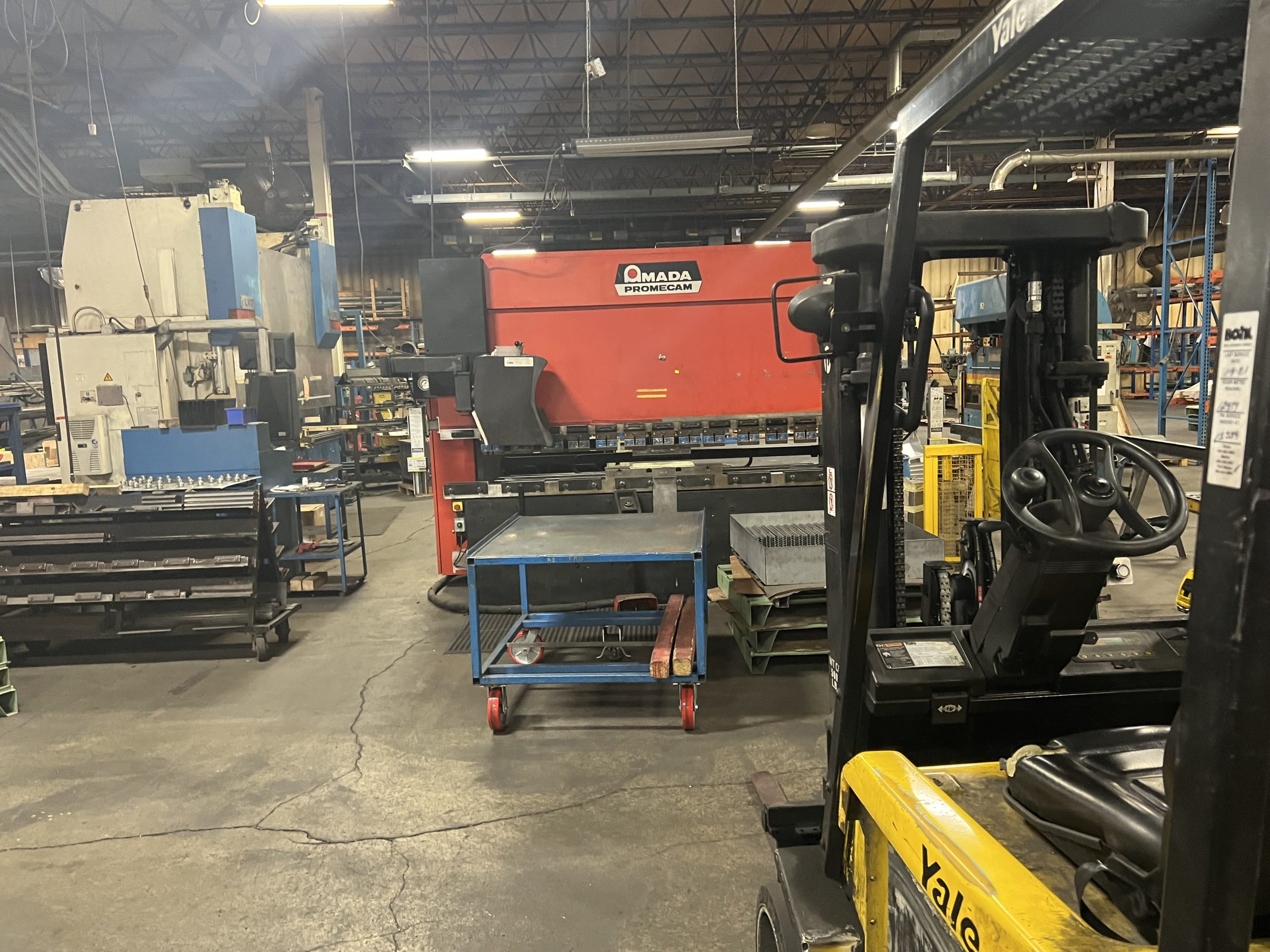
Production Execution
Approved designs move to our automated production floor:
Cutting: Amada LC-2415 laser cutters (±0.1mm accuracy) or turret punching (max. 6.4mm steel)
Bending: CNC press brakes with automatic tool changers (±0.25° angular tolerance)
Secondary Operations: Robotic welding (TIG/MIG), PEM insertion, deburring, and finishing (powder coat, anodizing)
Each batch includes first-article inspection (FAI) per AS9102 standards, with real-time SPC monitoring of critical dimensions. Material traceability is maintained via serialized barcoding from coil to shipment.
Delivery and Documentation
Completed parts undergo final QA against ASME Y14.5 GD&T requirements before packaging. Standard delivery includes:
Certified material test reports (MTRs)
FAI documentation with dimensional results
Packing list with serialized part tracking
As-built 3D model for design validation
Expedited shipping via DHL/FedEx with online tracking is standard, with typical lead times of 5–10 business days for prototypes and 10–15 for production runs. Rush services achieve 72-hour turnaround for qualified geometries.
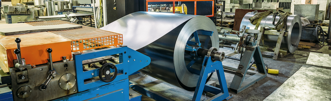
Material and Thickness Capabilities
| Material Type | Thickness Range | Max. Flat Size | Tolerance Standard |
|———————|—————–|—————-|———————|
| Mild Steel (CRS/HR) | 0.5–6.0 mm | 1500×3000 mm | ISO 2768-mK |
| Aluminum Alloys | 0.8–4.0 mm | 1250×2500 mm | ISO 2768-mK |
| Stainless Steel | 0.8–3.0 mm | 1000×2000 mm | ISO 2768-mK |
This closed-loop process integrates digital engineering with shop-floor execution to minimize time-to-part while ensuring compliance with aerospace, medical, and industrial quality requirements. All production data is archived for full traceability across the product lifecycle.
Start Your Project
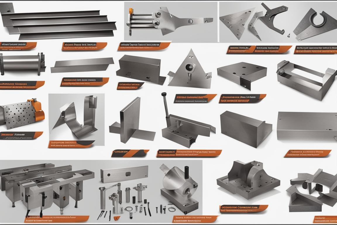
Explore our full range of precision sheet metal fabrication tools and equipment, engineered for performance and durability in high-demand manufacturing environments. From laser cutting and CNC punching to press braking and welding systems, we provide end-to-end solutions to support your production needs.
All equipment is manufactured and rigorously tested at our Shenzhen factory, ensuring consistent quality and reliability. As your trusted partner in prototyping and low-volume production, Honyo Prototype delivers industrial-grade capabilities with fast turnaround times.
For technical specifications, pricing, or custom configuration support, contact Susan Leo at [email protected]. Let’s build your next project together.
🚀 Rapid Prototyping Estimator
Estimate rough cost index based on volume.