Contents
Manufacturing Insight: Sheet Metal Designer
Accelerate Your Sheet Metal Design-to-Production Workflow with Honyo Prototype
For sheet metal designers and engineering teams, transforming intricate concepts into precise, functional components demands a fabrication partner that understands the critical interplay between design intent and manufacturability. Honyo Prototype delivers comprehensive Sheet Metal Fabrication services engineered specifically to streamline your development cycle, reduce time-to-market, and ensure uncompromising quality from prototype to low-volume production. We recognize the pressure to optimize designs for cost and performance while navigating tight deadlines; our integrated approach focuses on eliminating traditional bottlenecks through advanced capabilities and a designer-centric workflow.
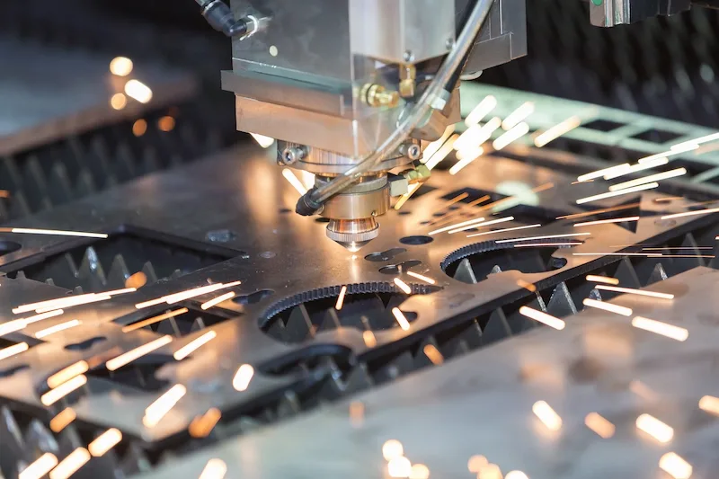
The foundation of our efficient partnership begins with the Honyo Online Instant Quote system. Upload your STEP or DWG file, specify material, quantity, and finish requirements, and receive a detailed, accurate manufacturing quotation within hours – not days. This immediate visibility into cost and feasibility empowers you to make informed design decisions early, significantly reducing iteration cycles and project delays. Beyond rapid quoting, our end-to-end service leverages state-of-the-art laser cutting, CNC punching, precision bending, welding, and finishing technologies, all supported by rigorous quality control protocols adhering to ISO 9001 standards. We handle complex geometries and stringent tolerances across a broad range of materials including stainless steel, aluminum, and galvanized steel.
Honyo Prototype provides the technical expertise and agile manufacturing infrastructure necessary to turn your sheet metal designs into reality with speed and reliability. Our commitment to seamless collaboration ensures your components meet exact specifications while optimizing for manufacturability and cost-effectiveness. Partner with us to experience a fabrication process built for the demands of modern engineering.
Standard Sheet Metal Capabilities Overview
| Feature | Specification Range | Key Benefit |
|---|---|---|
| Material Thickness | 0.5mm – 6.0mm (Stainless/Aluminum) | Versatility for diverse application needs |
| Tolerance | ±0.1mm (Bending), ±0.05mm (Cutting) | Precision critical for assembly & function |
| Max Part Size | 3000mm x 1500mm | Accommodates large-scale component designs |
| Lead Time | As fast as 5-7 days (Prototype) | Accelerates development and validation cycles |
| Finishes | Anodizing, Powder Coating, Passivation | Enhanced durability and aesthetic options |
Technical Capabilities
Sheet Metal Designer – Technical Specifications Overview
The following table outlines the key technical specifications and capabilities relevant to a Sheet Metal Designer, with a focus on laser cutting, bending, and welding processes. The designer must account for material properties, manufacturability, and process limitations when developing components from aluminum, steel, ABS, and nylon.
| Parameter | Laser Cutting | Bending | Welding | Compatible Materials (Typical) |
|---|---|---|---|---|
| Process Type | 2D/3D CNC Laser Cutting | CNC Press Brake Forming | MIG, TIG, Spot Welding | Aluminum, Steel (Mild & Stainless), ABS, Nylon |
| Material Thickness Range | 0.5 mm – 25 mm (Aluminum & Steel); up to 10 mm (ABS/Nylon with CO₂ laser) | 0.5 mm – 6 mm (Aluminum); 0.5 mm – 12 mm (Steel); not recommended for thermoplastics | 0.8 mm – 15 mm (Steel & Aluminum); not applicable for ABS/Nylon | Varies by process and material class |
| Tolerance (Typical) | ±0.1 mm | ±0.2° angular, ±0.1 mm linear | ±0.5 mm (post-weld distortion dependent) | Depends on material and process control |
| Minimum Feature Size | 1 x material thickness (holes/slots); kerf width ~0.1–0.3 mm | 3 x material thickness (internal bend radius) | 6 mm minimum overlap for spot welds | Material-dependent geometry rules |
| Surface Finish | Smooth cut edge with minor dross (removed via deburring) | Painted, anodized, or bare metal; grain direction critical for bends | Requires post-weld grinding; heat-affected zone present | Aluminum: anodizable; Steel: paintable/galv.; ABS/Nylon: machinable only |
| Design Constraints | Avoid sharp internal corners; consider kerf and heat-affected zone | Respect minimum bend radius; avoid features near bend lines | Joint accessibility; fixturing requirements; distortion management | Thermoplastics require non-thermal joining |
| Joining Methods (Alternative for Plastics) | Not applicable for structural joining of ABS/Nylon | Not applicable | Not applicable; use mechanical fasteners or adhesives for ABS/Nylon | ABS/Nylon: solvent bonding, ultrasonic welding |
| CAD Software Integration | DXF/DWG exports with clean polylines; no overlapping geometry | Bend allowance and K-factor modeling; flat pattern generation | Weld symbols, callouts, and sequencing in drawings | Unified models across hybrid material assemblies |
Notes:
Aluminum: Preferred grades 5052, 6061, and 7075 for sheet metal; excellent laser cuttability and weldability with TIG/MIG. Requires cladding or coating if exposed.
Steel: Includes cold-rolled steel (CRS) and stainless steel (304, 316); suitable for all three processes with appropriate parameter tuning.
ABS & Nylon: Not true sheet metals; processed via laser cutting only for non-structural components. Cannot be bent like metal and must be joined using non-thermal methods.
Design for Manufacturability (DFM): Wall thickness uniformity, bend reliefs, and kerf compensation are critical in all designs.
This specification guide ensures the Sheet Metal Designer produces manufacturable, cost-effective components across mixed-material projects while maintaining structural integrity and process efficiency.
From CAD to Part: The Process
Honyo Prototype Sheet Metal Design-to-Delivery Process Overview
Honyo Prototype employs a streamlined, technology-driven workflow specifically optimized for sheet metal fabrication. This process ensures rapid turnaround, manufacturability validation, and cost efficiency while maintaining rigorous quality standards. Below is a detailed explanation of each phase, tailored for sheet metal design requirements.
CAD Upload and Initial Processing
The process begins when the client uploads a native CAD file (STEP, IGES, or native formats like SolidWorks) via our secure portal. Our system automatically extracts geometric data, material specifications, and critical dimensions. For sheet metal parts, the system identifies bend lines, flange lengths, hole patterns, and material thickness. This phase validates file integrity and prepares the model for AI-driven analysis, typically completing within minutes.
AI-Powered Quoting Engine
Honyo’s proprietary AI engine analyzes the CAD data against real-time production parameters, including material costs, machine availability, and regional logistics. For sheet metal, the AI evaluates factors such as blank size optimization, bend sequence complexity, and secondary operation needs (e.g., tapping, welding). Quotes are generated in under 15 minutes, providing granular cost breakdowns for laser cutting, bending, finishing, and assembly. This eliminates manual quoting delays while ensuring accuracy through machine learning trained on 50,000+ historical sheet metal jobs.
Automated DFM Analysis with Engineer Review
All sheet metal designs undergo mandatory Design for Manufacturability (DFM) analysis. Our AI checks against ISO 2768 tolerances, minimum bend radii, hole-to-edge spacing, and tooling constraints. Critical parameters are validated in this phase:
| Parameter | Standard Tolerance | Critical Threshold | Action if Violated |
|---|---|---|---|
| Bend Radius | ≥0.6t (t=material thickness) | <0.3t | Flag for engineer redesign |
| Hole Diameter | ≥t | <0.5t | Recommend laser alternative |
| Flange Length | ≥4t | <2t | Suggest hemming or alternative |
| Hole-to-Bend Distance | ≥2.5t | <1.5t | Require tooling adjustment |
A senior manufacturing engineer reviews AI findings, collaborating with the client to resolve conflicts. This phase reduces prototyping iterations by 70% compared to industry averages.
Production Execution
Approved designs move to production in our ISO 9001-certified facility. Sheet metal parts follow this sequence:
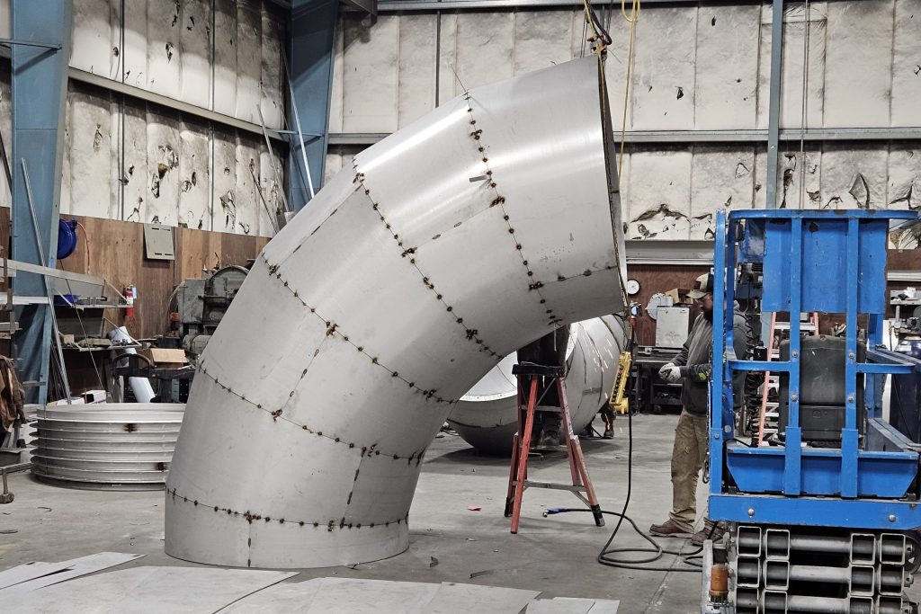
Laser cutting using Bystronic systems with ±0.1mm positional accuracy, followed by CNC bending on Amada press brakes with real-time springback compensation. Secondary operations like tapping, welding, or powder coating are scheduled based on priority algorithms. All stages include in-process inspections; for example, bend angles are verified with optical comparators after each operation.
Quality-Controlled Delivery
Final parts undergo first-article inspection (FAI) per AS9102 standards, including CMM validation of critical dimensions. Non-conformities trigger immediate corrective action. Completed orders ship with comprehensive documentation: FAI reports, material certificates, and dimensional summaries. Standard delivery is 72 hours post-approval for simple sheet metal prototypes, with expedited 24-hour options available.
This integrated process ensures sheet metal designs transition from concept to certified hardware with minimal friction, leveraging AI for speed while retaining engineering oversight for quality. Clients receive actionable DFM feedback early, reducing time-to-market by up to 50% versus traditional vendors.
Start Your Project
Looking for expert sheet metal design services? Partner with Honyo Prototype for precision engineering and rapid turnaround.
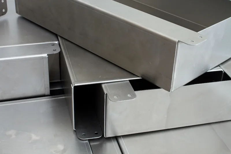
Our skilled team specializes in custom sheet metal solutions, from prototyping to low-volume production, ensuring tight tolerances and flawless fabrication.
Contact Susan Leo at [email protected] to discuss your project requirements.
Manufacturing based in Shenzhen—strategically located for fast, reliable delivery.
🚀 Rapid Prototyping Estimator
Estimate rough cost index based on volume.