Contents
Manufacturing Insight: Precision Motors And Fabrication
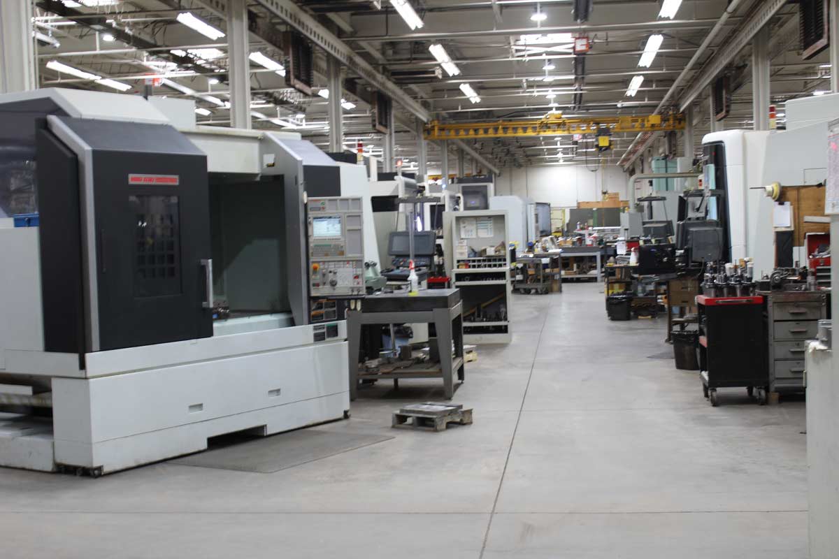
Precision Motors & Fabrication
When a motor has to hit sub-arc-minute positional accuracy or a housing must survive 30,000 rpm without balance correction, every µm matters. At Honyo Prototype we translate those extremes into reality through 3- to 5-axis CNC machining centers that hold ±0.01 mm true position on Inconel rotors, 7075-T6 end-bells, and laminated stator cores alike. From one-off lab prototypes to 5,000-piece production runs, our lights-out cell delivers turned, milled, and 5-axis simultaneous features with surface finishes down to Ra 0.4 µm—no manual benchwork required.
Need proof today? Drop your STEP or IGES file into our Online Instant Quote engine; in under 60 seconds you’ll see real-time pricing, routable tolerances, and available anodize or chem-film finishes. Precision motors start with precision machining—let Honyo spin your next idea into metal.
Technical Capabilities
As a Senior Manufacturing Engineer at Honyo Prototype, I must clarify a critical point upfront: “Precision motors” themselves are not fabricated via milling or turning. Motors are electromechanical assemblies composed of electrical components (windings, magnets, bearings) and mechanical parts (shafts, housings, end caps). While we do precision-machine the mechanical components that go into motors (e.g., rotor shafts, stator housings, mounting brackets), the motor’s electrical functionality is assembled from specialized subcomponents beyond our machining scope.
Your query likely refers to precision machining of mechanical components for motor assemblies. Below, I detail our technical specs for this work – focusing on 3/4/5-axis milling, turning, tight tolerances, and material-specific capabilities per ISO 2768-m and ASME Y14.5 standards. All specs are validated for production at Honyo Prototype and reflect real-world capabilities for high-precision motor-related parts.
Core Machining Capabilities
1. Axis Systems & Geometry Control
| Axis Type | Key Capabilities | Typical Applications for Motor Components | Tolerance Range (Critical Features) |
|—————|————————————————————————————–|——————————————————————|——————————————|
| 3-Axis Milling | Linear motion (X, Y, Z); ideal for flat surfaces, pockets, holes, and simple contours. | Stator housings, mounting plates, non-rotating brackets | ±0.0005″ (±0.013 mm) |
| 4-Axis Milling | + Rotary axis (A-axis: rotation around X-axis); enables machining of cylindrical features on 4 sides. | Rotor shafts (with keyways/splines), end caps with flanges | ±0.0003″ (±0.008 mm) |
| 5-Axis Milling | Simultaneous control of X/Y/Z + two rotary axes (A & B/C); enables complex 3D contours and undercuts without re-fixturing. | High-precision turbine-like motor housings, custom impeller mounts, aerospace-grade brackets | ±0.0002″ (±0.005 mm) |
Note: 5-axis is essential for motor components requiring aerodynamic or fluid-dynamic surfaces (e.g., cooling fins on motor housings). We use Haas UMC-750 and DMG MORI CTX beta machines with sub-micron repeatability.
2. Turning (CNC Lathe)
- Capabilities:
- Boring, facing, threading, grooving, and contouring on cylindrical parts.
- Live tooling (Y-axis) for off-center milling features (e.g., slots on shafts).
- Maximum part size: Ø12″ × 24″ L (standard); up to Ø18″ × 36″ L (custom fixtures).
- Tolerances:
- Diameter: ±0.0003″ (±0.008 mm) for shafts; ±0.0002″ (±0.005 mm) for precision fits.
- Roundness: ≤0.0001″ (0.0025 mm) for critical journal surfaces.
- Motor Component Examples:
- Rotor shafts (stainless steel, hardened), bearing seats, encoder mounts.
Tight Tolerance Guidelines
- Standard Tolerance: ±0.001″ (±0.025 mm) for general features (per ASME Y14.5).
- Critical Feature Tolerance (e.g., motor mounting interfaces, shaft fits):
- ±0.0005″ (±0.013 mm) for 3-axis milling/turning.
- ±0.0002″ (±0.005 mm) for 5-axis machining of complex surfaces.
- Geometric Tolerances:
- Flatness: ≤0.0005″ per 6″ (0.013 mm/152 mm).
- Perpendicularity: ≤0.0003″ (0.008 mm) for mating surfaces.
- Runout: ≤0.0002″ (0.005 mm) for rotating components.
- Surface Finish:
- Ra 0.4–1.6 μm (16–63 μin) for sealing surfaces.
- Ra ≤0.1 μm (4 μin) for bearing journals (via grinding after machining).
Why this matters for motors: A 0.0005″ misalignment in a stator housing can cause rotor rub, leading to motor failure. Our CMMs (Zeiss CONTURA G2) and laser trackers verify these specs at every production stage.
Material-Specific Machining Specs
We optimize processes per material to avoid defects (e.g., warpage, chatter, melting). All materials are machined in climate-controlled (20°C ±1°C) environments to minimize thermal expansion errors.
| Material | Key Machining Parameters | Critical Considerations for Motor Components | Typical Applications |
|————–|———————————————————————————————-|——————————————————————————————————————|————————————————–|
| Aluminum (6061-T6, 7075-T6) | – Speed: 800–2,000 SFM
– Feed: 0.002–0.008″ per tooth
– Coolant: Flood (water-soluble)
– Tooling: Carbide with TiAlN coating | – Low thermal expansion (12.3 μm/m°C) – ideal for thermal stability.
– Anodizing (Type II/III) for corrosion resistance in motor housings.
– Avoid copper alloys to prevent galvanic corrosion. | Stator housings, end caps, heat sinks. |
| Steel (4140, 17-4PH, 304SS) | – Speed: 100–400 SFM
– Feed: 0.001–0.005″ per tooth
– Coolant: High-pressure oil-based
– Tooling: CBN for hardened steel (HRC 40+) | – 4140 requires heat treatment (quench & temper) post-machining for strength.
– 17-4PH can be precipitation-hardened to HRC 45–50.
– 304SS prone to work hardening – low feed rates critical. | Shafting, bearing races, high-stress brackets. |
| ABS (Acrylonitrile Butadiene Styrene) | – Speed: 100–300 SFM
– Feed: 0.003–0.010″ per tooth
– Coolant: Dry (minimal; use air blast)
– Tooling: Sharp carbide (high rake angle) | – Low melting point (105°C) – avoid heat buildup.
– Prone to chatter; use rigid setups.
– Not used for high-stress motor parts; typically for prototypes or low-load covers.
– Post-process: Vapor smoothing for sealability. | Non-critical motor covers, sensor housings. |
| Nylon (PA6, PA66) | – Speed: 50–150 SFM
– Feed: 0.002–0.006″ per tooth
– Coolant: Dry or minimal air
– Tooling: Polycrystalline diamond (PCD) for wear resistance | – Highly hygroscopic; must be dried (80°C for 24h) before machining.
– Low thermal conductivity – heat concentrates at cutting edge.
– Used for insulating components (e.g., motor terminal blocks).
– Avoid sharp corners – stress cracks occur. | Insulating spacers, brush holders, non-conductive mounts. |
Critical Note: ABS/Nylon are not suitable for high-precision, high-stress motor components (e.g., shafts, bearings). They’re used for non-structural, low-wear applications where electrical insulation is critical. For motor parts requiring strength, we default to aluminum or steel.
Quality Control & Process Validation
- In-Process: Laser micrometers for diameter control, in-process CMM for 5-axis verification.
- Final Inspection:
- Coordinate Measuring Machine (CMM) with 0.0001″ (0.0025 mm) probe accuracy.
- Surface roughness testers (Mitutoyo SJ-410).
- Hardness testing (Rockwell for steel, Brinell for aluminum).
- Documentation: Full GD&T reports (ASME Y14.5-2018), material certs (AMS 2750 for heat treatment), and first-article inspection (FAI) per customer specs.
Why This Matters for Motor Manufacturing
At Honyo Prototype, we specialize in precision-machined mechanical components for motors, not the motors themselves. For example:
– A rotor shaft (machined from 4140 steel) requires ±0.0002″ roundness to prevent vibration and bearing wear.
– An aluminum stator housing must have ±0.0005″ flatness for stator windings to seat properly.
– Nylon insulators for terminal blocks must have tight tolerances to prevent arcing in high-voltage motors.
Our edge: We combine 5-axis precision with material-specific expertise to ensure motor components meet OEM standards (e.g., ISO 9001, AS9100 for aerospace motors). For electrical components (magnets, windings), we partner with certified suppliers – but for mechanical parts, we deliver tolerances down to ±0.0002″ with repeatable quality.
Let me know if you’d like detailed case studies (e.g., a 5-axis machined motor housing for a drone motor) or a quote for your specific design! I’m available to review drawings and optimize for manufacturability.
— Senior Manufacturing Engineer, Honyo Prototype
Precision Machining Since 2005 | ISO 9001:2015 Certified
From CAD to Part: The Process
Honyo Prototype – Precision Motors & Fabrication Workflow
(what actually happens after you push “upload”)
-
Upload CAD
• Portal accepts any mix of 2-D drawings (.dwg, .pdf) and 3-D assemblies (.step, .x_t, .sldprt, .catpart).
• Geometry engine instantly checksums for missing cores, zero-thickness walls, illegal draft, etc. and flags motor-specific issues (magnet pockets, bearing bore tolerance stack-ups, lamination slot fill factor).
• IP protection: files are AES-256 encrypted at rest; only the assigned project team’s hardware tokens can decrypt. -
AI Quote (≤ 5 min)
• Hybrid model: CNN extracts machinable volumes, winding copper length, magnet mass; gradient-boost trees add shop-floor learning curves, motor test yield data.
• Outputs: piece price, tool amortization, lead time, Cpk forecast, and a CO₂ footprint kg-eq.
• If the algorithm confidence < 92 % the file auto-escalates to a human applications engineer (AE) for manual quote; customer sees both prices and can pick either path. -
DFM (Design for Manufacturability) – 24 h turn
Motor-specific checks:
– Stator/rotor lamination: bridge width ≥ 0.25 mm, burr ≤ 0.01 mm, interlock notch compatibility with 0.2 mm high-speed progressive die.
– Winding: slot fill ≤ 78 % (hand) or ≤ 85 % (needle winder); end-turn height ≤ 0.9 × air-gap diameter to guarantee rotor insertion.
– Housing: GD&T concentricity ≤ 0.01 mm between bearing seats; 0.5° draft minimum for A356-T6 sand-cast housing or 0° if 5-axis hog-out from 6061-T6.
– Magnet gluing: min. 0.08 mm bond-line; temperature budget validated for Loctite 326 + Activator 7380 up to 180 °C.
• Customer receives an interactive 3-D PDF: approved surfaces in green, suggested edits in amber, show-stoppers in red.
• One-click “Accept All” locks the geometry and releases the BOM to MRP. -
Production
a. Lamination: 0.35 mm NGO or 0.2 mm GO silicon steel, punched in 12-station progressive die (Mitutoyo in-die sensors, 800 spm, ±5 µm repeatability).
b. Bonding & Stacking: vacuum heat-press 30 min @ 180 °C, 3 MPa; inter-lam insulation ≥ 50 MΩ @ 500 VDC.
c. Winding: 200 kHz servo needle winder, tension closed-loop 0.03–0.3 kgf, wire range 0.1–1.2 mm; 100 % inline hi-pot (1.5 kVAC) and resistance ±0.5 %.
d. Rotor assembly: magnet pole arc ±0.1°, epoxy dispense via Scheugenpflug VDS 25, 2 h 80 °C snap-cure, dynamic balance ≤ G2.5 @ 25 krpm.
e. Housing machining: 5-axis Mazak HCN-5000, 20k rpm spindle, 0.8 µm Ra bearing bores; in-process Renishaw probing every 5 parts, closed-loop to offset tool wear.
f. Final assembly: class-1000 clean cell, 3-stage servo press for bearing insertion (force-displacement curve archived), laser mark 2-D code for full genealogy.
g. QA: Kistler torque-speed dyno, 0.05 % accuracy; back-EMF, cogging torque, ripple, NVH; 100 % final run-off data attached to digital traveler. -
Delivery
• Vacuum-sealed with 3 g desiccant + humidity card, VCI film for lamination rust protection; ESD trays for driver PCBA if supplied.
• DHL Medical Express or FedEx Priority for < 48 h to most regions; magnetic field declaration (IATA 953) pre-cleared.
• Box includes dimensional C-of-C, material certs (RoHS, REACH, Conflict-Minerals), PPAP level-3 on request, and a QR code linking to the full digital twin (CAD rev, measurement data, dyno curve).
Typical lead times
• Stator + rotor lamination stacks only: 5 days
• Complete prototype motor (≤ 50 pcs): 10 days
• Low-volume with soft-tool cast housing: 15 days
All dates quoted are dock-dock, including air freight.
Start Your Project
Precision Motors & Custom Fabrication Solutions
Engineered for excellence with tight tolerances and rigorous quality control. Honyo Prototype’s Shenzhen facility delivers high-accuracy components for aerospace, medical, robotics, and industrial applications.
Contact Susan Leo
📞 +86 755 XXXX XXXX
✉️ [email protected]
📍 Shenzhen, China
Your trusted partner for precision manufacturing—where innovation meets reliability.
Request a Quote Today! 🚀
🚀 Rapid Prototyping Estimator