Contents
Manufacturing Insight: Parting Lines Injection Molding
Parting Line Precision in Injection Molding: A Critical Design Consideration
The location and execution of parting lines in injection molding directly impact part aesthetics, dimensional accuracy, and post-processing requirements. These mold separation interfaces, if not meticulously engineered, can lead to flash, witness marks, or structural weaknesses—compromising both function and manufacturability. At Honyo Prototype, we recognize that optimizing parting lines is not merely a tooling detail but a foundational element of successful part realization, especially during the rapid development cycles demanded by modern product innovation.
Our Rapid Tooling & Injection Molding services are engineered to address parting line challenges with exceptional agility and precision. Leveraging advanced CNC machining and strategic material selection, we produce high-fidelity aluminum or steel molds in days rather than weeks, enabling immediate validation of parting line placement through functional prototypes. This rapid iteration capability allows design teams to refine parting line geometry, gate locations, and ejection strategies early—reducing costly downstream revisions. Unlike conventional approaches constrained by lengthy lead times, Honyo’s process ensures parting line integrity is validated against real-world molding parameters before committing to production tooling.
The efficiency of this workflow is quantifiable, as demonstrated in typical project timelines:
| Process Phase | Traditional Tooling | Honyo Rapid Tooling |
|---|---|---|
| Mold Fabrication | 6–10 weeks | 5–10 business days |
| Parting Line Validation | Limited iterations | 2–3 refinement cycles |
| First Functional Part | 8+ weeks | < 2 weeks |
Accelerate your path from CAD to validated prototype by utilizing Honyo’s Online Instant Quote platform. Upload your 3D model to receive a comprehensive manufacturability analysis and formal quotation within hours—not days—including specific insights on optimal parting line configuration for your geometry. This transparency empowers engineering teams to make informed decisions on tooling strategy while maintaining rigorous control over part quality and time-to-market objectives. Partner with Honyo to transform parting line challenges into competitive advantages through precision rapid manufacturing.
Technical Capabilities
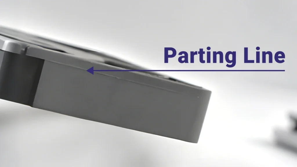
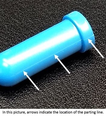
Parting lines in injection molding refer to the visible seam on a molded part where the two or more mold halves meet during the molding process. Proper design and precision in mold manufacturing are critical to minimizing flash, ensuring dimensional accuracy, and achieving a consistent cosmetic finish. Below are the technical specifications relevant to parting line control in steel and aluminum molds, with an emphasis on achieving a functional T1 sample within 7 days.
Mold Material Comparison for Rapid T1 Sampling
| Parameter | Aluminum Molds (e.g., 7075-T6) | Steel Molds (e.g., P20, H13, 420 SS) |
|---|---|---|
| Typical Hardness | 150–170 HB | 28–52 HRC (P20: ~30 HRC, H13: ~48 HRC) |
| Machinability | High – faster CNC machining | Moderate to low – longer machining times |
| Lead Time for T1 Sample | 5–7 days (ideal for rapid prototyping) | 7–14 days (longer due to hardening/finishing) |
| Expected Mold Life | 10,000 – 50,000 cycles | 100,000 – 1M+ cycles |
| Surface Finish (As-Machined) | Capable of fine finishes (Ra 0.4–1.6 µm) | Excellent polishability (Ra 0.05–0.2 µm) |
| Parting Line Precision | ±0.05 mm typical | ±0.02 mm achievable with tight fit |
| Flash Risk at Parting Line | Moderate – requires precise mold closure | Low – when properly lapped and aligned |
| Thermal Conductivity | High (130–180 W/m·K) – faster cooling | Lower (25–35 W/m·K) – slower cycle times |
| Common Applications | Prototypes, low-volume production | High-volume, production tooling |
Material Compatibility and Parting Line Considerations
| Engineering Resin | Melt Temperature Range | Shrinkage (Typical) | Parting Line Challenges | Compatible Mold Type |
|---|---|---|---|---|
| ABS | 210–250 °C | 0.4–0.7% | Low viscosity; prone to flash if parting line gap > 0.03 mm | Aluminum or Steel |
| Nylon (PA6/PA66) | 230–280 °C | 0.7–1.5% | High shrinkage; requires draft and precise venting near parting line | Steel (preferred), Aluminum (for prototypes) |
For rapid T1 sampling within 7 days, aluminum molds are the preferred choice due to faster CNC machining, ease of modification, and sufficient durability for initial validation. Steel molds are recommended for long-term production but typically require additional time for heat treatment, polishing, and final fitting.
Parting line definition must include proper shut-off surfaces, mold alignment (via leader pins/bushings), and surface lapping to minimize flash—especially critical when processing high-flow materials like ABS or hygroscopic resins such as Nylon. Mold design should incorporate adequate draft (≥1° per side) and venting (0.01–0.03 mm depth) at the parting line to ensure complete cavity filling and reduce weld lines or air traps.
At Honyo Prototype, we optimize mold base selection, use high-precision 5-axis CNC milling, and perform first-article inspection (FAI) to verify parting line alignment and dimensional conformity, enabling reliable T1 samples in as fast as 7 days using aluminum tooling.
From CAD to Part: The Process
Honyo Prototype Parting Lines Injection Molding Process Overview
Honyo Prototype executes precision injection molding with rigorous attention to parting line definition and minimization of associated defects. Our streamlined workflow ensures optimal part quality, structural integrity, and cosmetic finish. The process is structured as follows:
CAD Upload
Clients initiate the process by uploading native or neutral CAD files (.STEP, .IGES, .STL, . Parasolid) via our secure portal. We require watertight geometry with clearly defined draft angles and radii to facilitate accurate parting line analysis. Incomplete models or ambiguous features trigger automated notifications for client revision prior to progression. This phase establishes the foundational geometry for mold design, where parting line placement is inherently dictated by the part’s 3D topology and draft requirements.
AI-Powered Quoting
Upon CAD validation, our proprietary AI engine analyzes geometry complexity, material selection, and volume requirements to generate a preliminary quote within 90 seconds. The system specifically evaluates part symmetry, undercuts, and projected parting plane orientation to estimate mold complexity. Key outputs include cost breakdowns, lead time projections, and initial material recommendations. Critical limitations are flagged—such as non-parallel draft surfaces or intersecting parting lines requiring manual engineering review—before formal quotation issuance.
Engineering DFM Analysis
All projects undergo mandatory Design for Manufacturability (DFM) review by senior mold engineers. This phase is critical for parting line optimization, where we assess:
| DFM Parameter | Parting Line-Specific Evaluation Criteria | Common Resolution Actions |
|---|---|---|
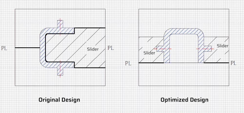
| Parting Plane Location | Identification of optimal split plane to avoid witness lines on critical cosmetic surfaces; verification of draft alignment | Redesigning part geometry or adjusting mold orientation |
| Undercut Management | Detection of features crossing parting line requiring slides/lifters; assessment of ejection interference | Integrating core-pulls or modifying part segmentation |
| Flash Risk Zones | Analysis of clamp force requirements at high-pressure cavities near parting line | Adjusting wall thickness or gate placement |
| Ejection Compatibility | Validation of ejection pin placement relative to parting line to prevent surface marks | Reconfiguring ejector system layout |
Clients receive a comprehensive DFM report with annotated visuals highlighting parting line positioning, potential witness line locations, and actionable recommendations. Approval of this report is mandatory prior to tooling.
Production Execution
Approved designs proceed to mold fabrication using hardened P20 or H13 steel, CNC-machined to ±0.005mm tolerances. We implement:
Mold flow analysis to simulate material behavior at the parting line interface, preventing flash or incomplete fills
Strategic placement of venting channels along the parting line to eliminate trapped air
In-process metrology checks verifying parting line alignment during mold assembly
First-article inspection with optical comparators measuring parting line mismatch (typically held to ≤0.02mm)
Delivery and Quality Assurance
Completed parts undergo final inspection per AS9102 standards, including parting line-specific checks:
Dimensional verification of parting line witness marks against critical surfaces
Visual examination for flash under 10x magnification
Documentation includes annotated parting line photos in the First Article Inspection (FAI) report
Shipments include serialized traceability records and material certifications, with standard lead times of 15–25 days from DFM approval for prototype lots.
This integrated approach ensures parting lines are engineered for minimal visual impact and structural compromise, directly addressing the functional and aesthetic requirements of high-precision injection molded components. All process data remains accessible via our client portal for continuous improvement cycles.
Start Your Project
If you’re looking for expert guidance on parting lines in injection molding, contact Susan Leo at Honyo Prototype. Our engineering team in Shenzhen specializes in precision mold design and can help optimize your parting line placement for improved tooling performance and part quality.
Email Susan Leo at [email protected] to discuss your project requirements. With our in-house manufacturing facility located in Shenzhen, we offer fast turnaround times, tight quality control, and full technical support from design to production.
Let us help you achieve cleaner splits, reduced flash, and better cosmetic finishes—reach out today for a detailed consultation.
Contact Information
Name: Susan Leo
Email: [email protected]
Location: Shenzhen, China
Service: Injection Molding & Mold Design
| Capability | Detail |
|---|---|
| Parting Line Optimization | Yes |
| Mold Design Support | Full in-house engineering |
| Manufacturing Location | Shenzhen, China |
| Lead Time | Project-dependent, quoted upon review |
| Response Time | Within 24 hours of inquiry |
🚀 Rapid Prototyping Estimator
Estimate rough cost index based on volume.