Contents
Manufacturing Insight: Offset Machining
Precision Through Offset Machining at Honyo Prototype
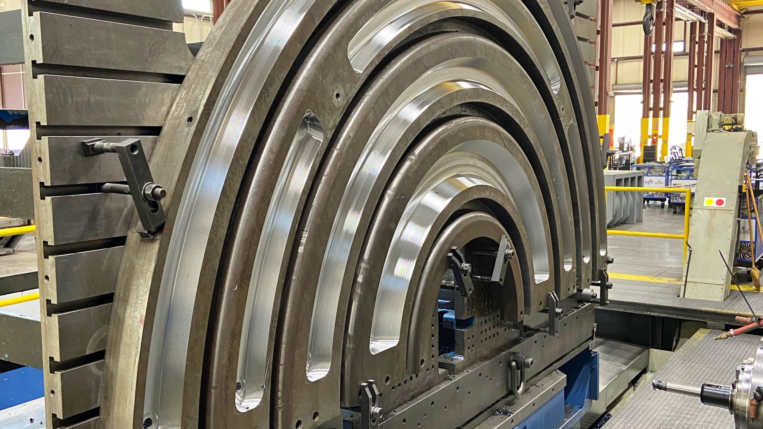
Offset machining represents a critical methodology in advanced CNC manufacturing, where toolpaths are strategically calculated at a defined radial or axial distance from the CAD model geometry. This technique is indispensable for achieving exacting tolerances on complex contours, undercuts, and multi-faceted features, particularly when utilizing ball-nose or radius-end mills. At Honyo Prototype, we leverage offset machining within our comprehensive 3-, 4-, and 5-axis CNC milling and turning capabilities to deliver components with superior surface integrity and dimensional repeatability. Our engineering team employs sophisticated CAM software to optimize toolpath compensation, minimizing manual intervention while ensuring first-article success for demanding aerospace, medical, and industrial applications.
Honyo Prototype’s commitment to precision extends beyond machining execution to seamless project initiation. Our proprietary Online Instant Quote platform provides immediate, transparent pricing and lead time estimates for CNC-machined prototypes and low-volume production parts. Simply upload your STEP or IGES file, specify materials and finishes, and receive actionable manufacturing feedback within hours—not days. This integration of technical expertise and digital efficiency ensures your offset machining requirements transition smoothly from design intent to certified physical part, accelerating time-to-market without compromising quality. Partner with Honyo to transform complex geometries into reliable, high-performance components through engineered precision and responsive service.
Technical Capabilities
Offset machining refers to a CNC machining strategy where the cutting tool follows a path that is offset from the final desired geometry, enabling precise material removal, improved tool life, and tighter dimensional control. This technique is widely used in 3-axis, 4-axis, and 5-axis milling operations, as well as in precision turning applications. It is especially critical when achieving tight tolerances (±0.005 mm to ±0.05 mm) across a variety of materials including aluminum, steel, ABS, and nylon.
The following table outlines key technical specifications and considerations for offset machining across different processes and materials:
| Parameter | 3-Axis Milling | 4-Axis Milling | 5-Axis Milling | CNC Turning |
|---|---|---|---|---|
| Axis Movement | X, Y, Z linear axes | X, Y, Z + rotary A-axis (rotates around X) | X, Y, Z + rotary A and B/C axes | X and Z linear axes + rotating chuck |
| Offset Strategy | 2D/3D contour offset, pocket milling | Rotary surface offset, helical interpolation | Multi-sided contour offset, tool tilt compensation | Diameter and face offset tool paths |
| Typical Tolerance | ±0.01 mm | ±0.01 mm | ±0.005 mm | ±0.005 mm to ±0.01 mm |
| Surface Finish (Ra) | 0.8 – 3.2 µm | 0.8 – 2.0 µm | 0.4 – 1.6 µm | 0.4 – 1.6 µm |
| Material Compatibility | Aluminum, Steel, ABS, Nylon | Aluminum, Steel, ABS | Aluminum, Steel | Aluminum, Steel, ABS, Nylon |
| Aluminum (e.g., 6061-T6) | High-speed offset paths; low cutting forces; coolant recommended | Rotary offset for complex features; high feed rates | Simultaneous 5-axis offset for deep cavities; minimal tool deflection | Precision diameter control; high RPM; sharp inserts |
| Steel (e.g., 4140, 17-4PH) | Rigid setups; reduced offset stepovers; carbide tools | Moderate feed/speed; incremental offset layers | High-precision tool orientation; reduced cycle time | Hard turning with CBN inserts; tight runout control |
| ABS (Thermoplastic) | Low thermal load; shallow offsets; sharp tools to prevent melting | Limited rotary use; avoid heat buildup | Not typical; used only for complex prototypes | Low feed rates; sharp cutting edges; minimal burring |
| Nylon (Polyamide) | Moderate speeds; controlled depth offsets; avoid galling | Limited due to flexibility; fixturing challenge | Rare; used for high-complexity prototypes | Careful clamping; sharp tools; consistent offset finishing passes |
| Tooling Requirements | End mills (2–4 flute for Al/ABS; 4–6 for steel) | Indexable or solid carbide with rotary compatibility | High-precision ball/square end mills; tool length compensation | Turning inserts (CNMG, WNMG); offset tool nose radius compensation |
| Fixturing | Vises, clamps, vacuum tables (for plastics) | Rotary tables with trunnions; alignment critical | 5-axis trunnion or swivel head; dynamic stability | Collets, chucks; steady rests for long parts |
| Applications | Flat surfaces, pockets, 2.5D profiles | Impellers, turbine blades, indexed features | Aerospace components, molds, medical implants | Shafts, bushings, threaded components |
Offset machining enhances accuracy and repeatability by compensating for tool diameter, wear, and geometry, particularly in high-precision environments. In multi-axis systems, dynamic offset adjustments allow for continuous tool engagement and improved access to complex geometries. When working with tight tolerances, proper offset calibration, thermal management, and material-specific cutting parameters are essential across all processes and materials listed.
From CAD to Part: The Process
Honyo Prototype utilizes precision CNC machining for rapid prototyping and low-volume production, commonly referred to in the industry as subtractive manufacturing or conventional CNC machining. The term “offset machining” is not a standard technical descriptor for this process; we interpret this query as addressing our end-to-end workflow for CNC-machined components. Below is a detailed explanation of our validated process flow:
CAD Upload and Initial Processing
Clients initiate the process by uploading native CAD files (STEP, IGES, Parasolid, or native formats like SLDPRT, IPT) via our secure customer portal. Our system performs automated geometry validation to confirm file integrity and manufacturability prerequisites. This step ensures dimensional coherence and identifies potential file corruption before proceeding to quoting.
AI-Powered Quoting Engine
Uploaded geometry is processed through Honyo’s proprietary AI quotation system. This engine analyzes part complexity, material requirements, tolerances, surface finishes, and secondary operations to generate a real-time cost estimate within 90 seconds. The algorithm cross-references historical machine utilization data, material market pricing, and labor benchmarks to ensure accuracy. Clients receive immediate visibility into lead times and cost drivers without manual intervention.
Engineering-Led DFM Analysis
Following quote acceptance, our manufacturing engineering team conducts a formal Design for Manufacturability review. This is not an automated step but a value-added engineering service where senior technicians evaluate:
Tool access limitations and optimal setup configurations
Material waste reduction opportunities
Tolerance stack-up feasibility against GD&T callouts
Recommended process sequencing to minimize secondary operations
Clients receive a detailed DFM report with actionable suggestions, typically within 4 business hours. This collaborative phase prevents costly redesigns during production.
Production Execution
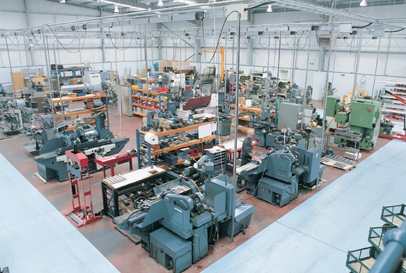
Approved designs move to our climate-controlled machine shop housing 42 CNC centers (3-axis vertical mills, 5-axis mills, and turning centers). Key production protocols include:
Material certification verification per AS9100 standards
First-article inspection using calibrated CMMs before full batch run
In-process gauging at critical operation transitions
Real-time machine monitoring for tool wear and dimensional drift
All machining adheres to ISO 2768 medium tolerance defaults unless tighter specifications are documented.
Quality-Controlled Delivery
Final inspection packages include:
Dimensional reports against critical features
Surface roughness validation via profilometer
Material certificate traceability
Packaging meeting ESD and shock-protection standards for sensitive components
Shipments include digital quality documentation accessible via client portal. Standard lead time from DFM approval is 5-7 business days for simple geometries in common materials.
Process Timeline Summary
| Process Stage | Typical Duration | Key Deliverable |
|---|---|---|
| CAD Upload | < 1 hour | Validated geometry confirmation |
| AI Quote Generation | < 2 minutes | Real-time cost/lead time estimate |
| DFM Analysis | 4-8 business hrs | Engineering review report |
| Production | 5-10 business days | Machined components with certs |
| Delivery | 1-3 business days | Trackable shipment with QC docs |
This integrated workflow reduces time-to-part by 40% compared to traditional machine shops through digital thread continuity from CAD to shipment. All processes comply with ISO 9001:2015 quality management standards, with optional AS9100 certification available for aerospace clients. We emphasize collaborative engineering throughout to ensure first-time-right outcomes for complex machined prototypes.
Start Your Project
Offset machining is a precision manufacturing process ideal for creating complex geometries with improved tool life and reduced cycle times. At Honyo Prototype, our Shenzhen-based factory leverages advanced CNC capabilities to deliver high-accuracy offset machining for prototyping and low-volume production.
For project inquiries or technical specifications, contact Susan Leo at [email protected]. Our engineering team is ready to support your design and manufacturing needs with fast turnaround and strict quality control.
🚀 Rapid Prototyping Estimator
Estimate rough cost index based on volume.