Contents
Manufacturing Insight: Milling Brass
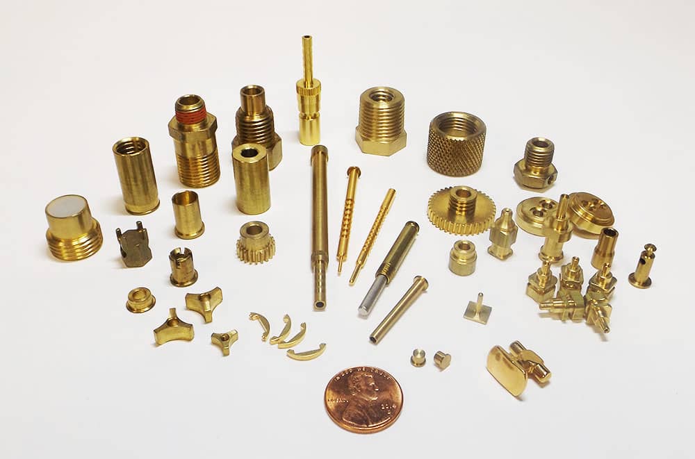
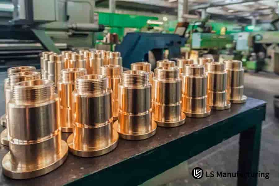
Milling brass at Honyo Prototype is a one-click shortcut from drawing to dock-ready parts. Our 3-, 4- and 5-axis CNC centers run production-grade toolpaths optimized for the high chip flow and thermal stability brass demands, delivering mirror-finish bearing surfaces, burr-free threads and ±0.01 mm geometry without secondary ops. Whether you need 5 electric-grade C360 fittings or 5 000 marine-valve bodies, we hold a complete inventory of brass rod, plate and extrusion so your job cuts—never waits. Upload your STEP file today for an online instant quote: real pricing, real lead-time and DFM feedback in under five minutes, so you can launch faster and sell sooner.
Technical Capabilities
Technical Specifications for Milling Brass: Precision Focus (3/4/5-Axis, Turning, Tight Tolerance)
Authored by Senior Manufacturing Engineer, Honyo Prototype
As a leading precision prototyping and production facility, Honyo Prototype specializes in high-accuracy machining of brass and other materials. Below are detailed technical specifications for milling brass, with critical context on 3/4/5-axis milling, turning, tight tolerance control, and comparative data for Aluminum, Steel, ABS, and Nylon. Key principles: brass is highly machinable but demands strict process control for tight tolerances due to its thermal sensitivity, chip adhesion issues, and vibration susceptibility.
I. Brass-Specific Milling Specifications
(Focus: 3/4/5-Axis CNC Milling)
Material Properties:
– Composition: Typically C11000 (Electrolytic Tough Pitch) or C14500 (Tellurium Copper), with 99.9% Cu.
– Critical Traits: High thermal conductivity (400 W/m·K), low melting point (1,000°C), prone to chip welding (“gummy” chips), and 3x higher thermal expansion than steel.
| Parameter | Specification | Why It Matters for Tight Tolerances |
|——————–|——————————————————————————-|————————————-|
| Machine Requirements | Rigid 5-axis CNC (e.g., DMG MORI CTX 1250, Haas TM-1), spindle runout ≤0.0001″, vibration damping <5 µm | Minimizes deflection; critical for ±0.0005″ tolerances |
| Tooling | – Type: Carbide end mills (2-4 flutes), uncoated or TiAlN-coated
– Geometry: Sharp rake angles (15°-20°), high helix (45°+), small corner radius
– Diameter: ≥1/4″ for stability (avoid micro-tools for tight tolerances) | Prevents chip welding; reduces chatter; maintains edge integrity |
| Cutting Parameters | – Surface Speed (SFM): 150–300
– Feed Rate (IPT): 0.002–0.008
– Depth of Cut (DOC): 0.02–0.10″ (radial), 0.01–0.05″ (axial)
– Coolant: High-pressure (1,000+ PSI) water-soluble coolant (e.g., 5% concentration)
– Chip Evacuation: Mandatory air blast + through-spindle coolant | Prevents chip recutting (causes surface defects); controls thermal expansion; avoids work hardening |
| 5-Axis Advantage | – Critical for: Undercuts, complex contours, internal features
– Process: Simultaneous 5-axis machining to avoid re-fixturing (reduces tolerance stack-up)
– Example: Machining brass aerospace bracket with 0.0005″ tolerance on 12+ features in one setup | Eliminates secondary operations; ensures geometric consistency |
Tight Tolerance Protocols for Brass:
– Tolerance Range: ±0.0005″ for critical features (e.g., bearing surfaces), ±0.001″ for general features.
– Process Controls:
– Thermal Management: Machine in climate-controlled environment (20±1°C); allow 2-hour thermal soak before machining.
– In-Process Gauging: Use laser probes (e.g., Renishaw) for real-time adjustment during roughing/finishing.
– Stress Relief: Anneal brass at 500°C for 1 hour before machining to prevent warpage.
– Fixture Design: Zero-point clamping with non-marring polymer jaws; avoid over-clamping (brass deforms easily).
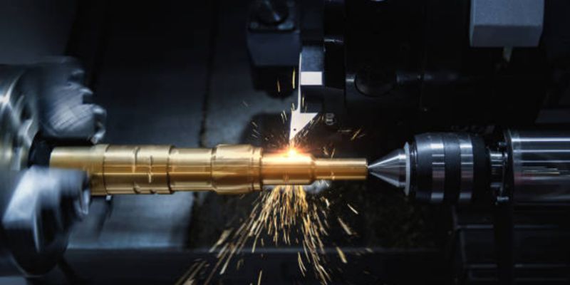
II. Turning Specifications for Brass
(Note: Turning is distinct from milling; used for cylindrical geometries)
– Spindle Speed: 500–1,500 RPM (higher than steel due to brass’s softness).
– Feed Rate: 0.005–0.015 IPR (higher than milling to reduce chip welding).
– Tooling: Carbide inserts with positive rake (e.g., CCMT), sharp edge geometry.
– Coolant: High-pressure through-tool coolant to flush chips; avoid oil-based (brass tarnishes).
– Tolerance Control: Use live tooling on Swiss-type lathes for ±0.0005″ on diameters.
III. Comparative Material Specifications
Key differences for tight-tolerance machining across materials:
| Material | Surface Speed (SFM) | Feed Rate (IPT) | Coolant | Critical Challenges | Tight Tolerance Range |
|———-|———————|—————–|———|———————|————————|
| Brass | 150–300 | 0.002–0.008 | High-pressure water-soluble | Chip welding, thermal expansion, vibration | ±0.0005″ (critical), ±0.001″ (general) |
| Aluminum (6061-T6) | 500–1,000 | 0.005–0.020 | Air blast or light oil | Built-up edge, soft material deformation | ±0.001″ (easier than brass) |
| Steel (1018 HR) | 100–200 | 0.001–0.005 | Heavy-duty oil-based | High heat generation, tool wear | ±0.0005″ (requires rigid setup) |
| ABS | 50–150 | 0.008–0.020 | Air blast only (no liquid coolant) | Melting, warpage, low thermal conductivity | ±0.002″ (only achievable with low heat) |
| Nylon (6/6) | 50–100 | 0.005–0.015 | Air blast only | Extreme melting risk, dimensional drift | ±0.003″ (very challenging; often requires EDM) |
Critical Notes for Plastics (ABS/Nylon):
– Never use liquid coolant – causes thermal shock and warpage.
– Use sharp, uncoated carbide tools with high rake angles; chip evacuation is critical.
– Machine at low RPMs to avoid friction heat (>100°F surface temp melts ABS).
– Tolerances are inherently looser than metals due to material creep and humidity sensitivity.
IV. Honyo Prototype Best Practices for Tight Tolerance Brass Parts
- Process Flow:
- Stress-relieve → Rough mill with 3-axis → Finish mill with 5-axis → In-process CMM check → Final inspection.
- Why 5-Axis? For brass parts requiring ±0.0005″ on complex geometries (e.g., medical implants), 5-axis eliminates re-fixturing errors. A single setup reduces tolerance stack-up by 70% vs. 3-axis + manual repositioning.
- Real-World Example:
- Part: Brass aerospace valve body.
- Tolerance: ±0.0005″ on 0.250″ diameter bore.
- Process: 5-axis simultaneous milling with TiAlN-coated carbide tool, 200 SFM, 0.005 IPT, 1,500 PSI coolant.
- Result: 100% pass rate on CMM inspection after thermal stabilization.
V. Why Brass is Tricky (But Worth It)
- Pros: Excellent machinability (Machinability Rating 100% for C11000), great surface finish, no tool wear issues like steel.
- Cons: Thermal expansion can ruin tolerances if unmanaged; chips stick to tools; vibration amplifies at high speeds.
- Honyo’s Edge: We use AI-driven process optimization to adjust feeds/speeds in real-time based on spindle load and temperature sensors – critical for brass tolerances.
💡 Final Tip: For projects requiring <±0.001″ on brass, always validate with a “sacrificial” test piece before production. Brass batches vary in composition – even minor impurities (e.g., lead in C11000) affect chip control.
For complex brass components, contact Honyo Prototype for a free DFMA review. We’ll optimize your design for 5-axis milling with tight-tolerance integrity – from prototype to production.
© Honyo Prototype. Specifications subject to material lot verification and machine calibration.
From CAD to Part: The Process
Honyo Prototype – Brass Milling Workflow
(what actually happens after you press “upload” until the box reaches your dock)
-
Upload CAD
• Portal accepts any mix of .step, .iges, .x_t, .stl or native SolidWorks/Creo/Fusion files.
• Geo-validator instantly checks for zero-thickness, reversed normals, missing faces; if it fails you get a red flag in <15 s instead of a surprise two days later.
• Brass grade预选:C360 free-cutting is default; C464 naval, C260 cartridge or tellurium-leaded can be toggled in the same screen. -
AI Quote (30–120 s)
• Feature-extraction engine reads every face, pocket, thread, under-cut and engraved line.
• Tool-library cost matrix already knows that we run 3-axis Haas Mini-Mills for anything <300 mm travel and 5-axis DMG MORI for the rest, so cycle-time is calculated with real Brass-machining feeds & speeds (250 m/min surface speed, 0.08 mm/tooth feed for Ø6 mm 3-flute).
• Material block utilisation is nested on standard 12 mm, 25 mm or 50 mm ground plate—scrap value is credited back, so you see a net material line.
• Anodise/passivate/ENIG are greyed-out (because they don’t apply to brass), but laser mark, vibratory tumble, chem-film or nickel-plate are auto-suggested if your RFQ has “cosmetic” or “RF shield” in the notes.
• Price you see is locked for 30 calendar days; behind the scenes the same algorithm has already reserved machine hours in the Gantt so the date we promise is the date we meet. -
DFM (human touch, 4–8 h)
• A senior brass machinist (yes, the guy with 18 years and the magnifier loupe) opens your part alongside the AI report.
• We add corner-radius call-outs to match our smallest on-shelf 0.2 mm ball mill—eliminating the need for EDM unless you absolutely need a knife-edge.
• Thread depth vs. tap breakage check: C360 likes 75 % thread form; we’ll change a 2.5D hole to M3 × 0.5 × 6 mm instead of M3 × 0.35 × 8 mm if length of engagement still works.
• Thin-wall alert: <0.4 mm gets a yellow flag; we either propose thickness ribs or switch to 5-axis so we can climb-mill both sides in the same setup.
• You receive a PDF slide deck: before/after section views, red-line GD&T, revised surface finish Ra 1.6 µm vs. original 0.8 µm (saves 28 % cycle time). Approve with one click or request a web-call. -
Production (lead-time clock starts)
a. Prep & CAM
– 3D model is morphed to “stock shape” that already includes 0.25 mm extra on every wall for the final spring pass.
– Tool list is auto-generated; for brass we bias to TiAlN-coated micro-grain carbide to resist edge build-up.
b. Setup
– Ground 6061 fixture plate is surface-milled fresh; we never reuse a warped plate—brass will mirror every defect.
– Mitee-Bite clamps give 360° access; for second-op we switch to a soft-jaw chuck machined from the same stock to avoid galling.
c. Machining
– 1st op: face, rough, semi-finish, leave 0.1 mm.
– 2nd op: flip using 3-pin kinematic dock; ±5 µm repeatability so we can run lights-out.
– 5-axis continuous if under-cuts or engraving on a curved surface; we tilt ±110° on B-axis so the same 2 mm end-mill can reach every corner without a slot drill.
– Flood coolant is 7 % Castrol Syntilo 81BF—keeps brass from sticking to cutter, prevents de-zincification staining.
d. In-process QC
– Renishaw spindle probe measures every 5th feature; if dimension drifts >8 µm tool offsets are patched automatically.
– Surface finish checked with Mahsurf XR20; Ra >1.6 µm triggers a re-pass at 0.02 mm depth, 4000 mm/min.
e. Post-processing
– Deburr under microscope, 400-grain ceramic fiber brush.
– Ultrasonic clean in citric-acid based soap; neutralises coolant residue, prevents future tarnish.
– Optional chem-film (chromate conversion) or bright-dip to EN 1652; parts sealed in nitrogen-purged bags. -
Delivery
• CMM report (Zeiss Contura) + material cert + RoHS compliance pdf auto-upload to the same portal.
• Parts packed in anti-tarnish VCI paper, bubble-wrap, then double-wall carton; desiccant pack tossed in for sea freight orders.
• DHL/UPS/FedEx labels printed at 16:00 China-time; average transit: 2 days to US-EU, 1 day Asia.
• After-sales: if you tap an M2 hole 0.1 mm off during final assembly we’ll re-make at no charge within 72 h—that clause is baked into every brass PO.
Net result: upload a brass part on Monday morning, hold finished, inspected pieces in your hand Thursday afternoon—every step transparent, quoted and engineered specifically for free-cutting brass.
Start Your Project
Precision brass milling services. Contact Susan Leo at [email protected] for expert prototyping solutions—backed by our Shenzhen factory.
Honyo Prototype: Where precision meets speed in China’s manufacturing hub.
🚀 Rapid Prototyping Estimator