Contents
Manufacturing Insight: Metal Prototype Fabrication
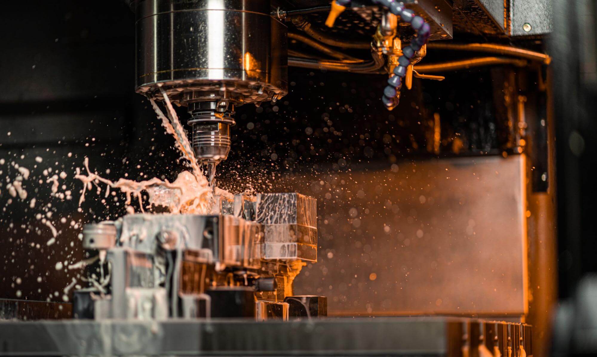
From flat-pattern to flight-ready in days—Honyo Prototype’s Sheet Metal Fabrication group turns 0.3 mm foils into 12 mm armor-plate prototypes with the same CNC precision we use on aerospace manifolds and EV battery enclosures. Upload your STEP, DXF or native SolidWorks file and our online instant-quoting engine returns a detailed DFMA report, blank development, bend radius confirmations and piece-part pricing in under 60 seconds. Whether you need one-off aluminum brackets, 48-hour stainless-steel weldments or pre-production galvanized chassis with PEM hardware, we laser-cut, form, hardware-insert, weld, finish and CMM-inspect in-house so your metal prototype ships fast, flat and functional—no minimums, no surprises.
Technical Capabilities
Technical Specifications for Metal Prototype Fabrication
(Important Clarification: ABS and Nylon are thermoplastics, not metals. They cannot be processed using metal-specific techniques like laser cutting, bending, or welding in a “metal fabrication” context. This document covers metal-only processes for Aluminum and Steel. For ABS/Nylon prototyping, we use CNC machining, 3D printing, or plastic-specific methods—see separate section at the end.)
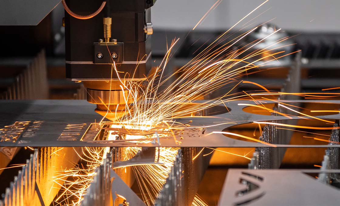
1. Laser Cutting (Metal-Specific)
Process: High-energy laser beam melts/vaporizes metal along a programmed path.
Materials:
– Aluminum (Al 6061, 5052, 7075):
– Max Thickness: 25 mm (with 4kW fiber laser)
– Tolerance: ±0.1 mm (standard), ±0.05 mm (precision)
– Edge Quality: Smooth, minimal dross on <6mm; may require post-processing for >6mm.
– Critical Notes: Oxide layer removal required pre-cutting; use nitrogen assist gas for clean edges.
– Steel (Mild Steel, Stainless 304/316):
– Max Thickness: 25 mm (mild steel), 20 mm (stainless)
– Tolerance: ±0.1 mm
– Edge Quality: Minimal heat-affected zone (HAZ) with oxygen assist for mild steel; nitrogen for stainless to prevent oxidation.
General Specs:
– Laser Type: Fiber laser (1kW–4kW) for metals (CO2 lasers less efficient for reflective metals like Al).
– Kerf Width: 0.1–0.3 mm (depends on material/thickness).
– Surface Finish: As-cut; post-processing (deburring, polishing) optional for critical edges.
– Design Constraints:
– Minimum Feature Size: 1.5x material thickness.
– Hole Diameter: ≥ material thickness (e.g., 2mm hole for 2mm sheet).
– Avoid sharp internal corners; use fillets ≥ 0.5x material thickness.
2. Bending (Metal-Specific)
Process: Press brake forming with dies to create angles, flanges, or complex shapes.
Materials:
– Aluminum (Al 6061, 5052):
– Minimum Bend Radius: 1.0x material thickness (e.g., 1.5mm for 1.5mm sheet).
– Springback: 2°–5° (requires overbending compensation).
– Surface Protection: Use plastic-coated dies to prevent scratches; avoid high-force bends on anodized surfaces.
– Steel (Mild Steel, Stainless 304):
– Minimum Bend Radius: 0.8x material thickness (mild steel), 1.5x (stainless due to work hardening).
– Springback: 1°–3° (mild steel), 3°–8° (stainless).
General Specs:
– Tolerance: ±0.5° for angles; ±0.1 mm for flange lengths.
– Die Width: 8x material thickness (e.g., 8mm die for 1mm sheet).
– Bend Allowance: Calculated per material (e.g., 0.45x thickness for Al 6061).
– Critical Notes:
– Grain direction must align with bend direction for ductility.
– Sharp bends on stainless steel may cause cracking—use larger radii.
– For painted/coated parts: Specify “bend before coating” to avoid paint damage.
3. Welding (Metal-Specific)
Process: Joining metal parts via fusion (MIG/TIG) or spot welding.
Materials:
– Aluminum (Al 6061, 5052):
– Process: TIG welding (preferred for precision), MIG for thicker sections.
– Pre-weld Prep: Remove oxide layer with stainless steel brush; use argon purge for critical joints.
– Post-Weld: Stress-relief annealing (for 6061); anodizing requires post-weld cleaning.
– Tolerance: ±0.2 mm for fit-up; distortion control via fixturing.
– Steel (Mild Steel, Stainless 304):
– Process: MIG (mild steel), TIG (stainless for aesthetics/corrosion resistance).
– Pre-weld Prep: Degrease surfaces; preheat for >10mm mild steel to prevent cracking.
– Post-Weld: Pickling for stainless to restore corrosion resistance.
General Specs:
– Joint Types: Butt, lap, fillet (standard for prototypes).
– Tolerance: ±0.3 mm for weld bead placement; ±1 mm for overall part alignment.
– Heat Input Control: Critical for thin materials (<2mm); use pulsed MIG or low-amp TIG to avoid warping.
– Quality Checks:
– Visual inspection for cracks/porosity.
– Dye penetrant testing for critical aerospace/medical parts.
⚠️ Critical Notes for Material Misconceptions
- ABS & Nylon are NOT metals—they are thermoplastics and cannot be processed with metal fabrication techniques:
- Laser Cutting: ABS/Nylon melt/vaporize unpredictably (high fumes, fire risk). Use CNC milling or plastic-specific lasers (e.g., CO2 at low power).
- Bending: Plastics require heat forming (not press brakes); bending angles are limited by material ductility.
- Welding: ABS/Nylon use plastic welding (hot air, ultrasonic) or adhesive bonding—not arc/MIG/TIG welding.
- Honyo Prototype Recommendation:
- For metal prototypes: Use the specs above for Aluminum/Steel.
- For plastic prototypes (ABS/Nylon): Specify CNC machining (±0.05 mm tolerance), FDM/SLA 3D printing, or vacuum casting.
Quality Assurance at Honyo Prototype
- All metal processes follow ISO 9001 standards.
- Pre-production checks: Material certs (e.g., Mill Test Reports), CAD/DFM review.
- Post-production: Coordinate Measuring Machine (CMM) verification for critical dimensions.
- Lead Time: 3–7 days for standard metal prototypes (laser-cut + bent/welded).
💡 Pro Tip: For hybrid metal/plastic assemblies (e.g., metal frame with ABS cover), specify separate processes for each material. We handle integrated prototyping with clear process boundaries—contact us for a DFM review!
Let me know if you need specs for ABS/Nylon plastic prototyping—happy to provide a separate document! 🛠️
From CAD to Part: The Process
Honyo Prototype – Metal Prototype Fabrication Workflow
(what happens after you press “Upload CAD” until the box reaches your dock)
-
Upload CAD
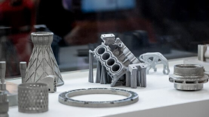
• Accepted formats: STEP, IGES, Parasolid, SolidWorks, Inventor, Creo, STL (for additive parts).
• Cloud gateway performs instant geometry repair: stitched solids, duplicate face removal, healing to ±1 µm.
• Encryption: AES-256 in transit and at rest; only the assigned project team can decrypt. -
AI Quote (≤5 min)
• Geometry analyser extracts 200+ features (wall, pocket, deep-hole, under-cut, sharp internal corner, etc.).
• Machine-learning model (trained on 1.3 M historical jobs) selects the optimal routing: 3-axis, 5-axis, turn-mill, EDM, wire, laser, or hybrid.
• Real-time stock pricing pulls LME aluminium, 303/304/316 SS, Ti-6Al-4V, CuCrZr, brass, magnesium and engineering plastic bar prices.
• Tolerance risk engine flags impossible call-outs (e.g., ±5 µm on a 200 mm long, 0.5 mm thin aluminium wall) and auto-suggests relaxed tolerance or design change.
• Output: itemised quote (material, set-up, machining time, finish, inspection, freight) with confidence score ≥97 %.
• Customer clicks “Accept” → project number issued, capacity reserved on the shop-floor MES. -
DFM (Design-for-Manufacture) – 24 h turnaround
• Dedicated senior manufacturing engineer (SME) reviews the AI flag list and runs a second-level check in Siemens NX + Vericut.
• Key DFM points for metal prototypes:
– Min radii: end-mill ≥0.2 mm, turning ≥0.05 mm.
– Aspect ratio for blind holes: ≤3 × diameter for Ø ≤1 mm, ≤6 × for Ø ≥3 mm.
– Deep-pocket rule: L/D ≤4 without relief; ≥4 requires stepped roughing or EDM.
– Thread relief: 2 × pitch undercut to avoid thread tearing during tapping.
– Weld prep: 30–45° bevel, root opening 1–2 mm for TIG prototype weldments.
• Customer receives PDF + 3D markup; approval is electronic. Any design change triggers delta-quote in <30 min. -
Production
a. Material & Setup
• Lot-controlled bar/plate from ISO-9001 mill; certificate uploaded to IQMS.
• Vacuum-packaged Ti and Mg alloys go straight to inert storage; moisture <30 % RH.
b. Programming & Simulation
• Mastercam / HyperMill tool paths verified in Vericut 9.2; G-code locked with checksum.
c. Machining
• 3- and 5-axis Mikron & Hermle centres (±3 µm positioning).
• Turn-mill (Star SR-38, Nomura NN-20) for ≤Ø65 mm round parts.
• Wire EDM (Sodick AP250L) for razor-sharp internal corners ≤R0.03 mm.
• In-cycle Renishaw probing: first-article dimensions captured and auto-compensated.
d. Surface & Heat Treatment
• As-machined Ra 0.8–1.6 µm standard; optional bead-blast, anodise Type II/III, chem-film Al, passivation SS, Ti anodise colour, electroless nickel, hard chrome, PVD.
• Stress-relief or T6 aging done in-house for aluminium; Ti solution-treated in vacuum furnace.
e. QC & Inspection
• 100 % dimensional check on critical-to-function (CTF) features; CMM report (Zeiss Contura G2) provided.
• Material cert, ROHS/REACH, and ITAR-controlled jobs kept in segregated cells.
f. Assembly & Kitting (if required)
• Helicoil, PEM, rivet-nut, dowel pinning; Loctite primer cured under LED UV.
• Functional tests (leak, torque, pressure) recorded in MES. -
Delivery
• Parts ultrasonically cleaned, sealed in VCI foil, bubble-bagged, boxed with silica gel.
• Courier choices: DHL Express (default), FedEx, UPS, or customer collect.
• Digital Dossier emailed: inspection report, material certs, packing list, MSDS for finishes.
• Typical lead-times:
– CNC only: 3–5 days.
– CNC + anodise/passivate: 5–7 days.
– Multi-process (CNC + EDM + heat-treat + PVD): 7–10 days.
• After-sales: 30-day dimensional warranty; rapid rework or re-make at no cost if fault is ours.
Throughout the flow, customers have live access to the Honyo Portal: real-time photos, CMM data, and ETA updates.
Start Your Project
Precision Metal Prototyping – Contact Susan Leo at [email protected] | Shenzhen-Based Factory
Fast, accurate, and reliable manufacturing for your next project. Let’s bring your designs to life. 🔧
🚀 Rapid Prototyping Estimator