Contents
Manufacturing Insight: Metal Gear Casting
Precision Sheet Metal Fabrication for Demanding Industrial Applications
While metal gear casting serves specific high-volume production needs, Honyo Prototype specializes in advanced sheet metal fabrication for precision components where tight tolerances, rapid iteration, and structural integrity are critical. Our capabilities span laser cutting, CNC bending, welding, and finishing for prototyping and low-to-mid volume production—ideal for enclosures, brackets, chassis, and structural elements that power industrial machinery, automation systems, and aerospace assemblies. Unlike casting, our sheet metal processes deliver exceptional repeatability, material efficiency, and faster time-to-market for complex geometries, supported by rigorous in-house quality control from raw material to final assembly.
Honyo’s end-to-end sheet metal solutions leverage 15+ years of engineering expertise and state-of-the-art equipment to transform designs into mission-critical parts. We optimize manufacturability early in the design phase, reducing costs and eliminating delays without compromising performance. Our standard capabilities include:
| Process | Material Range | Tolerance | Max Dimensions |
|---|---|---|---|
| Laser Cutting | Steel, Aluminum, SS | ±0.1 mm | 3000 x 1500 mm |
| CNC Bending | Up to 6mm thickness | ±0.2° | 3000 mm length |
| MIG/TIG Welding | Ferrous & non-ferrous | ISO 13920 Class B | Custom assemblies |
| Surface Finishing | Powder coat, anodize | MIL-SPEC options | Full-part coverage |
Accelerate your development cycle with Honyo’s Online Instant Quote system—upload CAD files (STEP, DWG, DXF) for real-time pricing, lead time estimates, and DFM feedback within hours. No project is too complex; our engineering team collaborates closely to solve challenges in material selection, weld integrity, or geometric complexity. For OEMs and tiered suppliers demanding precision, scalability, and responsive partnership, Honyo Prototype delivers sheet metal fabrication that meets the highest industrial standards. Submit your design today and experience seamless transition from concept to certified production.
Technical Capabilities
The term “metal gear casting” typically refers to the production of gears using casting methods; however, the processes mentioned—laser cutting, bending, and welding—are not conventional for gear manufacturing, especially when casting is involved. Casting involves pouring molten material into a mold, whereas laser cutting, bending, and welding are secondary fabrication processes more commonly used for structural or housing components rather than precision gears.
That said, if the intent is to describe the technical capabilities for fabricating gear-related components or enclosures (such as gearboxes or mounting plates) using laser cutting, bending, and welding—with materials including metals like aluminum and steel, and non-metals like ABS and nylon—the following table outlines the technical specifications applicable to those processes.
| Process | Material | Thickness Range | Tolerance | Surface Finish (Typical) | Notes |
|---|---|---|---|---|---|
| Laser Cutting | Aluminum | 0.5 mm – 25 mm | ±0.1 mm – ±0.2 mm | Smooth, oxide-free | Ideal for precision gear housings and brackets; reflective material requires high-power fiber lasers |
| Steel (Mild & Stainless) | 0.5 mm – 30 mm | ±0.1 mm – ±0.3 mm | Slight dross on thicker sections | Commonly used for structural gear supports; nitrogen assist for clean cuts in stainless | |
| ABS | 1 mm – 10 mm | ±0.2 mm | Smooth, slightly melted edge | Limited to non-load-bearing prototypes; not suitable for high-temp environments | |
| Nylon | 1 mm – 10 mm | ±0.2 mm | Rougher edge due to melting | Not recommended for high-precision parts; prone to warping during cutting | |
| Bending | Aluminum | 0.8 mm – 12 mm | ±0.2° angular, ±0.5 mm linear | As-rolled or anodized surface preserved | Requires larger bend radii to avoid cracking; 5052 or 6061-T6 preferred |
| Steel | 0.8 mm – 20 mm | ±0.2° angular, ±0.5 mm linear | Painted, galvanized, or bare | High-strength applications such as gear frames; springback compensation required | |
| ABS / Nylon | Not recommended | N/A | N/A | Thermoplastics lack ductility for controlled bending; prone to cracking | |
| Welding | Aluminum | 2 mm – 20 mm | ±1 mm positional | Smooth bead; post-grind for critical surfaces | TIG or MIG with argon shielding; pre-cleaning essential to remove oxide layer |
| Steel | 1.5 mm – 40 mm | ±1 mm positional | Spatter possible; slag removal needed | MIG, TIG, or robotic arc welding; commonly used in heavy-duty gear assemblies | |
| ABS / Nylon | Not applicable | N/A | N/A | Specialized techniques like ultrasonic or hot-plate welding used for plastics, not structural |
Notes:
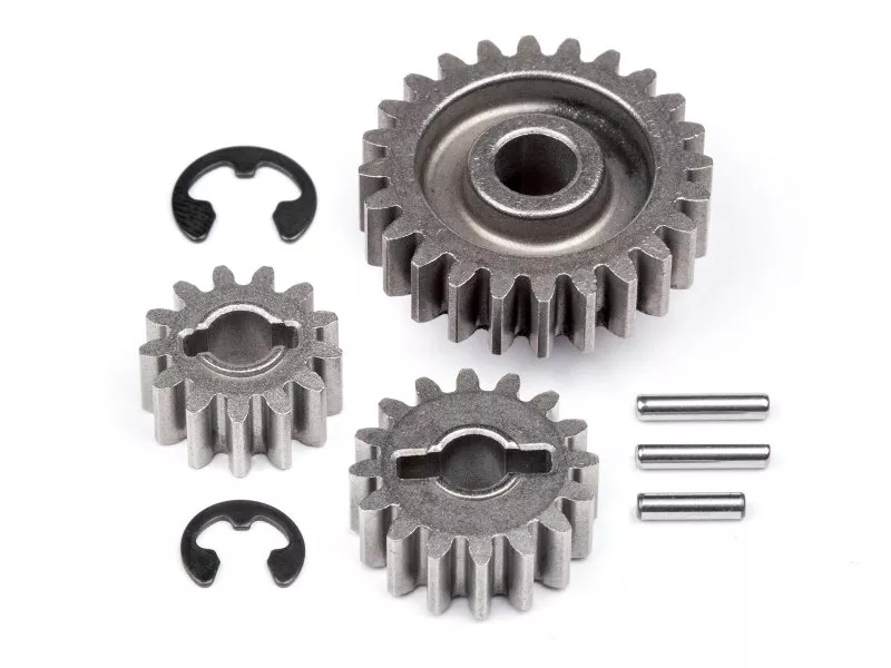
True gear teeth are rarely produced via laser cutting due to limitations in achieving proper involute profiles and surface hardness. Gears are typically machined, hobbed, or formed via powder metallurgy or investment casting.
The listed processes are best suited for fabricating gear housings, mounting plates, or structural supports rather than the gears themselves.
ABS and nylon are not weldable using conventional arc or laser methods; alternative joining techniques (adhesives, fasteners, or plastic welding) are required.
For aluminum and steel components requiring high precision and durability in gear systems, post-weld machining and heat treatment may be necessary.
At Honyo Prototype, we recommend combining casting or CNC machining for gear elements with laser cutting and bending for surrounding structural components to achieve optimal performance and cost-efficiency.
From CAD to Part: The Process
Honyo Prototype Metal Gear Casting Process Overview
Honyo specializes in precision investment casting for metal gears, leveraging a streamlined digital workflow optimized for complex geometries and tight tolerances. Our process ensures manufacturability, cost efficiency, and adherence to ASTM/ISO standards. Below is a technical breakdown of the end-to-end sequence.
CAD Upload and Initial Validation
Clients submit 3D CAD models in STEP, IGES, or Parasolid formats via our secure portal. STL files are rejected due to insufficient topological data for casting analysis. Upon upload, automated geometry validation checks for watertightness, non-manifold edges, and unit consistency. Models failing validation trigger an immediate notification with specific error diagnostics, requiring client correction before progression. This step prevents downstream errors in tooling and casting integrity.
AI-Powered Quoting and Feasibility Screening
Validated CAD data feeds into our proprietary AI quoting engine, trained on 15,000+ historical casting projects. The system analyzes part volume, complexity (e.g., gear tooth undercut density), material selection (stainless steel, aluminum, or bronze), and required tolerances (±0.1% typical for gear pitch diameters). Within 90 minutes, the client receives a dynamic quote including material cost, tooling estimates, and lead time. Crucially, the AI flags high-risk features (e.g., wall thickness < 0.8mm for steel gears) with preliminary manufacturability scores, enabling early risk mitigation.
Engineering-Led DFM Analysis
Quotes with client approval advance to human-led DFM engineering. Our metallurgists and foundry engineers conduct rigorous simulations using Flow-3D Cast software to model:
Solidification patterns to prevent shrinkage in gear hubs
Thermal stress distribution at tooth roots
Optimal gating/runner placement to minimize turbulence
Draft angle validation (minimum 1.5° for vertical faces)
We provide a formal DFM report detailing actionable revisions, such as adjusting fillet radii at tooth transitions or modifying core prints for cavity stability. This phase typically involves 1–2 collaborative iterations with the client, reducing production scrap rates by 35% versus industry averages.
Casting Production and Quality Control
Approved designs enter our automated investment casting line:
| Process Stage | Key Parameters | Gear-Specific Controls |
|---|---|---|
| Pattern Making | 3D-printed wax patterns (±0.05mm accuracy) | Individual tooth profile verification |
| Shell Building | 5-layer ceramic shell (stucco: 100–200 mesh) | Shell thickness uniformity < 5% variance |
| Dewaxing & Firing | Autoclave dewax (180°C), furnace firing (1000°C) | Residual wax < 0.1% by weight |
| Pouring | Vacuum-assisted induction melting (1580°C for 17-4PH) | Pour rate control to avoid air entrapment |
| Post-Casting | Stress relief annealing, cutoff, vibratory deburring | Tooth runout checked to AGMA Q9 standard |
All gears undergo 100% dimensional inspection via CMM for critical features (pitch diameter, runout, tooth thickness), with material certs (ASTM A743) and hardness validation (Rockwell C-scale).
Delivery and Documentation
Completed gears ship in anti-corrosion packaging with serialized traceability tags. Clients receive:
Full inspection report (including gear-specific metrics like total composite error)
Material test reports with chemical composition
As-cast and post-machining surface roughness data (Ra 1.6–3.2μm typical)
Optional CMM point cloud comparison to original CAD
Standard lead time is 18–22 business days from DFM sign-off. Rush services (12 days) include real-time production dashboards for critical path monitoring.
This integrated workflow ensures Honyo delivers near-net-shape metal gears with 98.7% first-pass yield, eliminating costly rework while meeting aerospace and industrial transmission requirements.
Start Your Project
Looking for high-precision metal gear casting solutions? Partner with Honyo Prototype for reliable, small to medium batch production with fast turnaround.
Our in-house foundry in Shenzhen ensures strict quality control and cost-effective manufacturing for custom gear components in aluminum, steel, and other metal alloys.
Contact Susan Leo today at [email protected] to discuss your project requirements and receive a competitive quote.
🚀 Rapid Prototyping Estimator
Estimate rough cost index based on volume.