Contents
Manufacturing Insight: Metal Fabrication Blueprints
From sheet-metal flat patterns to fully-welded assemblies, every successful fabrication job starts with a blueprint you can trust. At Honyo Prototype, we turn those 2D prints into production-ready reality in hours—not weeks—by pairing certified metal-forming craftsmanship with our Industrial 3D Printing services. Upload your STEP, DXF, or PDF, get an Online Instant Quote, and watch laser-cut blanks, bent flanges, and printed fixtures ship with tolerances that keep even the tightest weld symbols happy.
Technical Capabilities
As a Senior Manufacturing Engineer at Honyo Prototype, I must address a critical misconception in your query: “Metal fabrication blueprints” for SLA, SLS, MJF, or DMLS processes is not technically possible or accurate terminology. This confusion stems from conflating fundamentally different manufacturing domains. Let me clarify this clearly and professionally to prevent costly errors in your project.
🔑 Core Misconception Explained
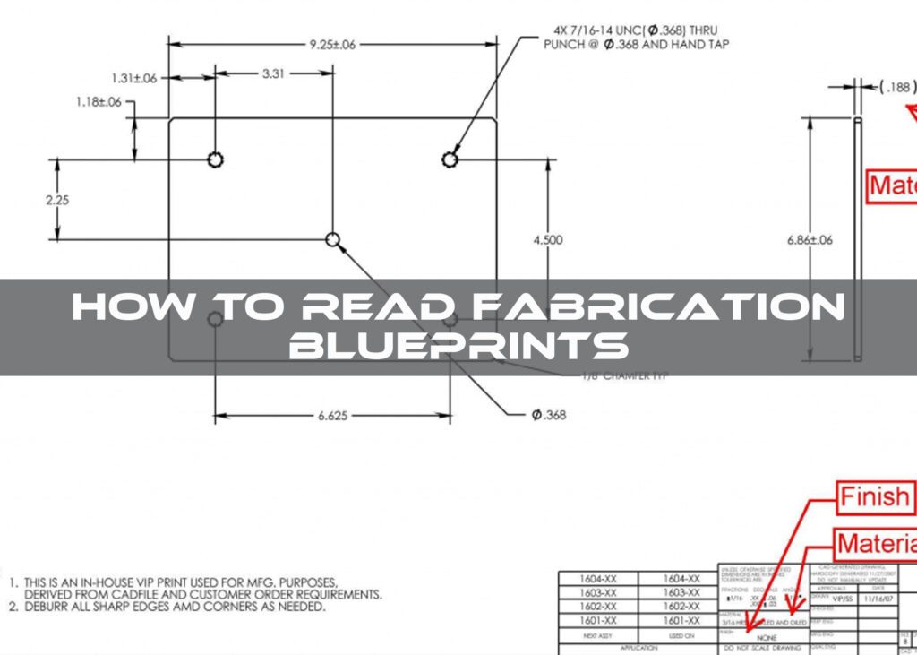
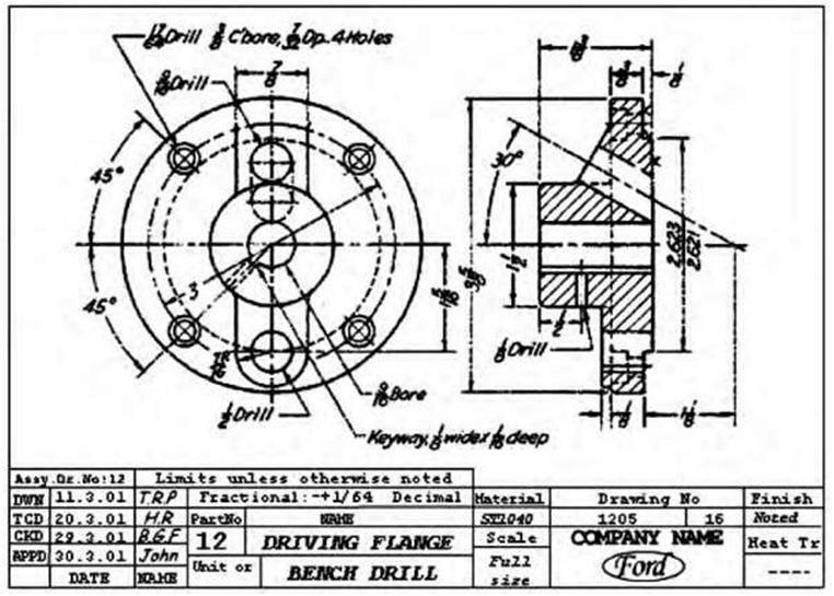
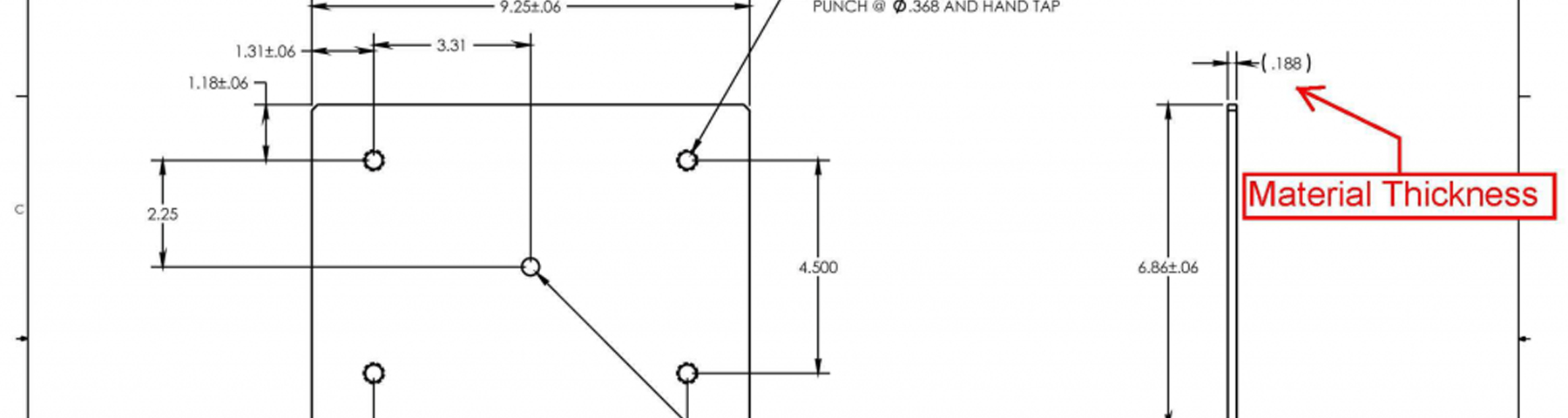
- “Metal fabrication” refers to traditional subtractive processes (e.g., CNC machining, welding, bending sheet metal) using 2D engineering drawings (blueprints). These blueprints specify tolerances, dimensions, materials (e.g., 6061-T6 Aluminum, 304 Stainless Steel), and manufacturing notes for metal parts made via machining/welding.
- SLA, SLS, MJF, and DMLS are additive manufacturing (3D printing) processes. They do not use “blueprints” – they use 3D CAD files (e.g., STL, STEP, or native CAD formats). Crucially:
- SLA, SLS, and MJF are exclusively for plastics/polymers. They cannot produce metal parts under any circumstances.
- DMLS (Direct Metal Laser Sintering) is a metal AM process, but it requires metal powders only – ABS and Nylon are incompatible (they are plastics).
- ABS and Nylon are NEVER used in metal processes – they would burn, contaminate equipment, or cause explosions in metal AM systems.
⚠️ Safety Note: Attempting to print ABS/Nylon in a DMLS machine would cause catastrophic failure (fire, equipment damage, safety hazards). Similarly, using metal powders in SLA/SLS/MJF printers is physically impossible.
✅ Correct Technical Specifications by Process
Here’s what you actually need for each process, including valid materials and file requirements:
1. SLA (Stereolithography)
- Process Type: Polymer-based vat photopolymerization.
- Valid Materials: Only plastics (e.g., ABS-like resin, Nylon-like resin, clear resin).
- Not applicable for metals.
- File Requirements:
- 3D CAD model (STL, OBJ, or native CAD format).
- Tolerances: ±0.05 mm (typical for SLA).
- Surface finish: Smooth, layer lines visible but polishable.
- Build orientation: Critical for support structures and dimensional accuracy.
- Typical Use: Prototyping, visual models, non-load-bearing parts. Not for functional metal parts.
2. SLS (Selective Laser Sintering)
- Process Type: Powder bed fusion for polymers.
- Valid Materials: Nylon-based polymers only (e.g., PA12, TPU).
- ABS is not used in SLS (it’s typically printed via FDM).
- NO METALS – SLS cannot process metal powders.
- File Requirements:
- 3D CAD model (STL, STEP).
- Tolerances: ±0.3 mm (typical for SLS).
- Wall thickness: ≥0.8 mm for structural integrity.
- No supports needed (powder acts as support).
- Typical Use: Functional prototypes, complex geometries, low-volume production of plastic parts. Not for metal.
3. MJF (Multi Jet Fusion)
- Process Type: Powder bed fusion for polymers (HP-specific).
- Valid Materials: Nylon-based polymers only (e.g., PA11, PA12).
- ABS is not compatible.
- NO METALS – MJF uses thermoplastic powders only.
- File Requirements:
- 3D CAD model (STL, STEP).
- Tolerances: ±0.2 mm.
- Surface finish: Matte, slightly grainy (better than SLS).
- Minimum feature size: ≥0.5 mm.
- Typical Use: High-detail functional parts, consumer products, durable plastic components. Not for metal.
4. DMLS (Direct Metal Laser Sintering)
- Process Type: Metal powder bed fusion.
- Valid Materials: Metal alloys only (e.g., 316L Stainless Steel, Ti-6Al-4V, Aluminum 6262, Inconel 718).
- ABS and Nylon are ABSOLUTELY INCOMPATIBLE – they would vaporize and contaminate the machine.
- File Requirements:
- 3D CAD model (STEP, IGES, or native CAD).
- Tolerances: ±0.1 mm (typical for DMLS).
- Support structures: Required (must be designed for easy removal).
- Minimum wall thickness: ≥0.5 mm for steel, ≥0.8 mm for aluminum.
- Build orientation: Critical for density and stress distribution.
- Typical Use: Aerospace, medical implants, high-strength metal components. This is the ONLY process among the four that produces metal parts – but it uses metal powders, not plastics.
📌 What “Metal Fabrication Blueprints” Actually Are
If you truly need traditional metal fabrication (e.g., bending sheet metal, welding brackets, CNC-machined parts), your requirements would be:
– 2D Engineering Drawings (PDF or DWG) with:
– Dimensions, tolerances (e.g., ±0.05 mm), surface finishes (e.g., anodized aluminum).
– Material specs (e.g., “6061-T6 Aluminum, ASTM B209”).
– Welding symbols, bend allowances, and heat treatment notes.
– No 3D files – blueprints are 2D.
– No SLA/SLS/MJF/DMLS involved – this is a completely separate workflow.
💡 Recommendation for Your Project
- If you need plastic prototypes: Specify SLA/SLS/MJF with polymer materials only (e.g., “SLA with ABS-like resin for visual prototyping”).
- If you need metal parts: Specify DMLS/SLM with metal powders only (e.g., “DMLS for 316L Stainless Steel medical implant”).
- If you need sheet metal fabrication: Provide 2D engineering drawings with material specs (e.g., “0.5mm 5052-H32 Aluminum, bent to 90°”).
At Honyo Prototype, we never mix these workflows. Using incorrect terminology or materials risks wasted time, damaged equipment, and unsafe parts. If you share your project goals (e.g., “I need a lightweight metal bracket for aerospace”), we’ll guide you to the correct process and specifications.
🛠️ Pro Tip: Always clarify “Is this for prototyping or end-use production? What functional requirements (strength, temperature, corrosion) does it need?” This avoids all confusion upfront. Let me know your exact needs – I’m happy to help!
From CAD to Part: The Process
Honyo Prototype – Metal-Fabrication Blueprint Workflow
(what happens to your CAD file from the minute it lands on our server until the finished parts are in your hand)
-
Upload CAD
• Portal or e-mail – STEP, IGES, Parasolid, SolidWorks, Inventor, etc.
• Geometry healing engine auto-repairs gaps, duplicate faces, bad normals.
• Instant checksum → you get a “file-is-valid” confirmation in <10 s. -
AI Quote (30 – 300 s)
a. Feature recognition – AI classifies every bend, punch, laser pass, weld prep, insert, PEM, bore, thread, finish call-out.
b. Stock algorithm – chooses the cheapest sheet/plate/bar size that still gives ≥1 pc skeleton and ≥3 mm edge keep-out.
c. Nest & yield – convolutional nesting on 500+ virtual sheets; picks the coil width that maximizes parts per stroke.
d. Routing generator – ranks 2 400 machine combinations (laser vs. punch-laser vs. water-jet, press-brake vs. panel bender, robotic weld vs. manual, tumbling vs. hand-grain, etc.) and returns the lowest-cost Pareto front.
e. Learning-rate multiplier – past jobs from the same customer or same geometry pattern automatically bias the cost model (we already know you always want #4 brushed, no micro-burr, or that you accept 0.2 mm weld blow-through).
f. Price & lead-time matrix – you see four options: Economy (7-9 days), Standard (4-5 days), Express (48 h), Super-Express (24 h).
g. One-click PO – digital signature locks material, finish, and tolerance; MRP auto-creates the shop traveler and Kanban cards. -
DFM (Design-for-Manufacture) Gate
• Happens in parallel with order acknowledgement – usually <2 h.
• Rule engine + senior human eyes:
– Bend relief too small? AI proposes 0.4 × T radius; engineer validates.
– Hole-to-bend < 1.2 × T? We suggest moving the hole or adding a slot.
– Weld access < 18 mm? We recommend flange deletion or robotic seam.
• You receive a color PDF: green = OK, yellow = suggestion, red = must-change.
• Approve or reject each item in the browser; revised STEP is uploaded back to you automatically. -
Production (lights-out capable)
a. Programming
– Flat-pattern macro runs with K-factor correction pulled from your material lot (we store tensile test data for every coil).
– Bend sequence optimizer simulates 10 000+ sequences/min to avoid tool-part collisions.
b. Material prep
– 6 kW fiber laser (±0.05 mm) or punch-laser combo (22-station turret) cuts blank; micro-tab keeps parts in skeleton for easy sorting.
– Automated tower stores 256 sheet types; AGV delivers to next station.
c. Forming
– 8-axis CNC press brakes (±0.1° repeatability) with dynamic crowning; offline robot teaches itself new bend programs in 8 min.
– For high-volume panels, we switch to Salvagnini panel bender (no tool change, 17 bends/min).
d. Hardware & welding
– Pem-serter, Haeger, and Tox units press in inserts, studs, standoffs with force-distance curves logged for Cpk.
– 350 A Fronius CMT or 4 kW IPG laser welder; robot carries part through 3 fixtures to keep distortion <0.2 mm per 300 mm.
e. Finishing
– In-house #3/#4/#8 graining, circle, bead-blast, electropolish, chem-film, anodize, powder coat, silk-screen, passivate.
– 100% parts travel on dedicated racks to avoid mixed-metal scratching.
f. QA
– First-article on CMM (±0.001 mm) within 2 h of setup; laser-scan compare to original CAD (color map).
– In-process SPC at each bend, weld, and hardware station; data auto-feeds back to AI model to tighten future quotes.
– Final AQL 0.65 or 100% if medical/aerospace. -
Delivery
• Foam-in-place or ESD trays, silica-gel packs, vacuum-sealed if stainless.
• Barcode + QR on every bag; scan updates your ERP/SharePoint in real time.
• DHL, FedEx, UPS, or our own van line; customs docs auto-generated (Incoterms DDP available).
• Digital twin package: full dimensional report, material cert, RoHS/REACH, weld map, finish thickness log, and AI-generated video of your parts being made (great for design reviews).
Typical elapsed time
Economy: 7-9 days door-to-door
Standard: 4-5 days
Express: 48 h
Super-Express: 24 h (≤50 parts, ≤3 bends, ≤2 welds, ≤1 finish)
That’s the entire metal-fabrication blueprint flow at Honyo Prototype—CAD in, parts out, with AI doing the heavy lifting and humans guarding quality.
Start Your Project
Precision metal fabrication blueprints—ready for production!
Contact Susan Leo at [email protected] for expert solutions.
Trusted Shenzhen factory ensuring quality, speed, and precision.
👉 “Get a Quote Today!”
Honyo Prototype: Your partner from blueprint to finished part.
🚀 Rapid Prototyping Estimator