Contents
Manufacturing Insight: Machining Tolerance Standards
Precision Engineering Through Defined Tolerance Standards at Honyo Prototype
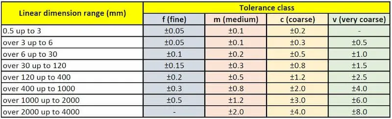
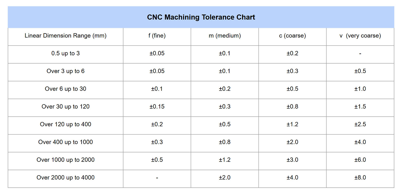
Achieving dimensional accuracy is non-negotiable in precision CNC machining, where tolerances directly impact part functionality, assembly integrity, and end-product performance. At Honyo Prototype, our CNC machining services are engineered around rigorously defined tolerance standards to eliminate ambiguity and mitigate prototyping risks. We adhere to ISO 2768 medium (m) as our baseline for general machining, ensuring consistent quality for standard applications while maintaining full capability to achieve tight tolerances down to ±0.005 mm for critical features. This disciplined approach extends beyond nominal specifications; our processes account for material behavior, thermal dynamics, and tool deflection to deliver geometric dimensioning and tolerancing (GD&T) compliance that meets aerospace, medical, and industrial design requirements.
Honyo’s tolerance framework is integrated into our digital manufacturing ecosystem, enabling seamless translation of engineering intent into physical reality. Unlike generic shops that treat tolerances as isolated metrics, we optimize toolpaths, fixturing, and in-process inspection around your specified limits—reducing scrap rates and accelerating time-to-prototype. For immediate project validation, our Online Instant Quote platform allows engineers to upload CAD files and select tolerance classes upfront, generating transparent pricing and lead times within minutes. This eliminates estimation delays while ensuring manufacturability feedback aligns with your precision targets from the earliest design phase.
By standardizing tolerances without compromising flexibility, Honyo transforms precision from a cost driver into a strategic advantage—delivering prototypes that perform as intended, every time.
Technical Capabilities
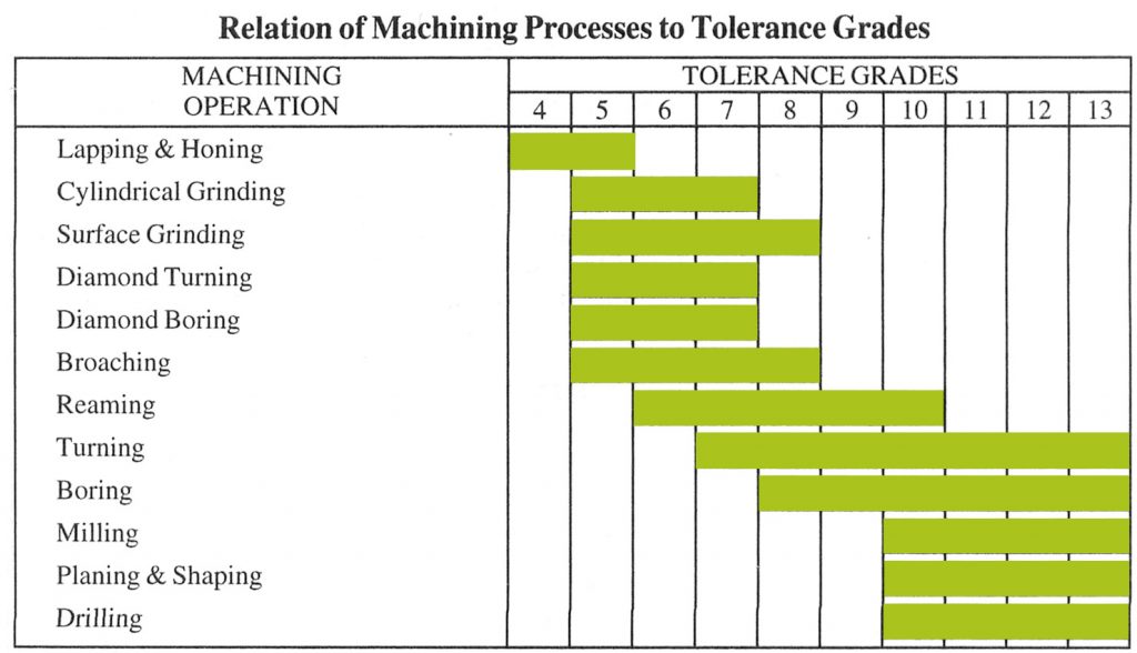
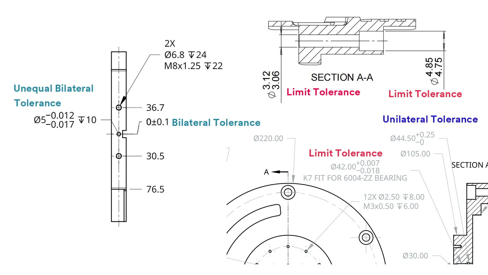
Machining tolerance standards define the allowable deviation in dimensions and geometry of machined components. For precision manufacturing involving 3, 4, and 5-axis milling and turning operations, tolerances are influenced by machine capability, tooling, fixturing, material properties, and part geometry. Tight tolerance machining typically refers to dimensional tolerances within ±0.005 mm (±0.0002″) or tighter, depending on the feature and material.
Below is a summary of typical achievable machining tolerance standards for common engineering materials under high-precision CNC conditions.
| Operation | Material | Dimensional Tolerance (Typical) | Geometric Tolerance (Typical) | Notes |
|---|---|---|---|---|
| 3/4/5-Axis Milling | Aluminum (6061, 7075) | ±0.0125 mm (±0.0005″) | ±0.025 mm (±0.001″) flatness/profile | Excellent machinability; minimal thermal deformation; suitable for tight tolerance work |
| 3/4/5-Axis Milling | Steel (4140, 1018, Stainless 304/316) | ±0.0125 mm (±0.0005″) | ±0.025 mm (±0.001″) flatness/profile | Higher cutting forces and heat generation; may require stress-relieved stock for stability |
| 3/4/5-Axis Milling | ABS | ±0.05 mm (±0.002″) | ±0.1 mm (±0.004″) flatness/profile | Lower stiffness; prone to deflection and thermal expansion; not ideal for tight tolerance |
| 3/4/5-Axis Milling | Nylon (PA6, PA66) | ±0.1 mm (±0.004″) | ±0.2 mm (±0.008″) flatness/profile | High moisture absorption and creep; dimensional instability limits precision |
| CNC Turning | Aluminum | ±0.01 mm (±0.0004″) | ±0.02 mm (±0.0008″) concentricity/cylindricity | High spindle accuracy enables tight diameter and runout control |
| CNC Turning | Steel | ±0.01 mm (±0.0004″) | ±0.02 mm (±0.0008″) concentricity/cylindricity | Requires rigid setup and sharp tooling; coolant critical for thermal control |
| CNC Turning | ABS | ±0.05 mm (±0.002″) | ±0.1 mm (±0.004″) concentricity | Soft material; prone to chatter and burring; limited precision |
| CNC Turning | Nylon | ±0.1 mm (±0.004″) | ±0.2 mm (±0.008″) concentricity | Low melting point and high elasticity affect surface finish and dimensional repeatability |
Notes on Tight Tolerance Machining:
For applications requiring tight tolerances (e.g., aerospace, medical, optics), additional process controls are implemented, including:
Use of high-precision CNC machines with sub-micron resolution and thermal compensation.
In-process probing and post-machining CMM inspection.
Stress-relieved or pre-machined and aged materials to minimize distortion.
Specialized tooling (e.g., PCD or CBN inserts) and optimized cutting parameters.
Environmental control (temperature, humidity) in metrology and machining areas.
Aluminum and steel are most suitable for tight tolerance machining due to dimensional stability and machinability. ABS and nylon are generally limited to less demanding tolerances due to inherent material variability.
From CAD to Part: The Process
Honyo Prototype maintains rigorous machining tolerance standards through a tightly integrated five-stage workflow designed to ensure dimensional accuracy, process reliability, and client transparency from initial inquiry to final delivery. This structured approach minimizes ambiguity and aligns manufacturing capabilities with client specifications at every phase.
Upon CAD file upload, our system initiates automated geometric and tolerance analysis against Honyo’s internal capability matrix. This matrix defines baseline tolerances for each material and process—for example, ±0.05 mm for milled aluminum features under 100 mm—and flags deviations requiring explicit client confirmation. The uploaded model’s annotations are cross-referenced with industry standards (ASME Y14.5, ISO 2768) to identify ambiguous or unrealizable callouts before quoting commences.
The AI Quote engine then generates a preliminary cost and timeline estimate while performing real-time tolerance feasibility scoring. It evaluates critical dimensions against machine tool capabilities (e.g., 5-axis CNC positional accuracy of ±0.005 mm) and material behavior (e.g., thermal expansion in brass). Tolerances tighter than Honyo’s standard capability trigger automatic cost modifiers and technical queries embedded in the quote, ensuring clients understand implications of extreme precision requests before commitment.
During DFM analysis, our engineering team conducts a dual-layer tolerance validation. First, automated checks verify adherence to geometric dimensioning principles and detect conflicts between tolerances and feature geometry. Second, a senior manufacturing engineer performs manual review focusing on tolerance stack-up risks, measurement methodology feasibility, and cost-impact analysis. Key outcomes include:
Confirmation of achievable tolerances per feature
Recommendations for tolerance relaxation where possible
Identification of critical-to-quality (CTQ) dimensions requiring specialized inspection
Documentation of any client tolerance overrides with engineering justification
Tolerance standards are enforced during production through controlled process parameters and nested inspection protocols. Machine tool paths incorporate in-process probing for critical dimensions, while final inspection uses calibrated CMMs, optical comparators, or surface roughness testers per the documented inspection plan. All measurements trace to NIST-certified standards with full reporting against the original CAD model’s tolerance callouts.
Delivery includes comprehensive quality documentation where tolerances are validated. Each shipment contains:
First Article Inspection (FAI) report with actual vs. nominal measurements for CTQ dimensions
Dimensional certification for all tolerance-critical features
Material certification and process validation records
Traceability logs linking components to machine tools and inspection equipment used
This closed-loop process ensures tolerances are not merely specified but actively managed and verified. Below is a summary of Honyo’s baseline machining tolerance capabilities for common materials under standard production conditions:
| Material Category | Feature Type | Standard Tolerance | Tight Tolerance Option | Measurement Method |
|---|---|---|---|---|
| Aluminum Alloys (6061, 7075) | Linear Dimensions | ±0.05 mm | ±0.0125 mm | CMM with 0.001 mm resolution |
| Steel Alloys (1018, 4140) | Hole Diameter | +0.025/-0.000 mm | +0.005/-0.000 mm | Air gauging or plug gauges |
| Brass (C36000) | Profile Tolerance | ±0.075 mm | ±0.025 mm | Optical comparator |
| Plastics (Delrin, Nylon) | Flatness | 0.1 mm per 100 mm | 0.05 mm per 100 mm | Surface plate with dial indicator |
Honyo’s process eliminates tolerance-related surprises by embedding standards compliance into each workflow transition. Client CAD inputs define requirements, AI quoting establishes feasibility boundaries, DFM optimizes for manufacturability, production executes with verified controls, and delivery provides auditable proof—ensuring parts meet functional requirements while maximizing cost efficiency.
Start Your Project
For detailed information on our machining tolerance standards, contact Susan Leo at [email protected]. Our precision manufacturing facility in Shenzhen adheres to strict quality controls, ensuring consistent accuracy and repeatability across all machined components. Let us support your project with tight-tolerance capabilities and expert engineering insight. Reach out today to discuss your requirements.
🚀 Rapid Prototyping Estimator
Estimate rough cost index based on volume.