Contents
Manufacturing Insight: Machining Threads
Precision Thread Machining: Engineering Reliability into Every Connection
Achieving precision threads in demanding applications requires more than standard machining—it demands exacting control over geometry, surface finish, and material integrity to ensure leak-free seals, structural integrity, and assembly reliability. At Honyo Prototype, our advanced CNC machining capabilities specialize in producing critical threaded features to exacting standards, including ISO, UN/UNF, NPT, and custom profiles, across aerospace alloys, medical-grade stainless steels, and high-performance polymers. Our multi-axis CNC centers, coupled with in-process probing and post-machining CMM validation, eliminate common pitfalls like thread runout, burring, or inconsistent pitch diameters that compromise functional performance.
We understand that thread integrity directly impacts your product’s lifecycle and safety compliance. That’s why Honyo integrates thread milling, single-point threading, and rigid tapping with stringent process controls, ensuring concentricity tolerances down to ±0.0002″ and surface finishes as fine as Ra 8 μin. Our engineering team collaborates early to optimize thread design for manufacturability, reducing scrap rates and accelerating time-to-assembly without sacrificing quality.
For rapid project initiation, leverage Honyo’s Online Instant Quote platform. Upload your CAD file to receive a detailed, geometry-aware quote in under 60 seconds—complete with lead time estimates and material cost breakdowns—so you can move from design validation to precision-threaded prototypes faster. Reduce prototyping delays with manufacturing expertise engineered into every thread.
| Capability | Specification Range | Key Standards Supported |
|---|---|---|
| Thread Types | External/Internal, Straight/Tapered | ISO 68-1, ASME B1.1, NPT |
| Tolerance Control | ±0.0002″ concentricity | AS9100, ISO 1302 |
| Material Compatibility | Titanium, Inconel, PEEK, 17-4PH | AMS, ASTM, ISO |
| Surface Finish | Ra 8 μin (typical) | ISO 1302 |
Technical Capabilities
Technical Specifications for Machining Threads – 3/4/5-Axis Milling and Turning – Tight Tolerance Applications
Machining threads with high precision in multi-axis environments (3, 4, and 5-axis milling) and turning operations requires a combination of advanced tooling, precise programming, and material-specific considerations. The following table outlines key technical parameters and capabilities for thread production across common engineering materials, with emphasis on tight tolerance performance (±0.0005″ to ±0.001″ typical).
| Parameter | 3-Axis Milling | 4-Axis Milling | 5-Axis Milling | CNC Turning | Notes |
|---|---|---|---|---|---|
| Max Thread Size | M24 (3/4″-10 UNC) | M24 (3/4″-10 UNC) | M24 (3/4″-10 UNC) | M36 (1″-12 UNF) | Larger sizes possible with form tools in turning |
| Min Thread Size | M2 (2-56 UNF) | M2 (2-56 UNF) | M2 (2-56 UNF) | M3 (4-40 UNF) | Limited by tool strength and access |
| Threading Method | Tapping, Single-Point Milling | Indexing + Milling | Simultaneous 5-axis helical interpolation | Single-Point Threading, Form Threading | 5-axis allows compound angle threading |
| Typical Tolerance | ±0.001″ (±0.025 mm) | ±0.001″ (±0.025 mm) | ±0.0005″ (±0.013 mm) | ±0.0005″ (±0.013 mm) | Tighter tolerances achievable with gauge-grade tooling |
| Surface Finish (Ra) | 32–64 μin (0.8–1.6 μm) | 32–64 μin (0.8–1.6 μm) | 16–32 μin (0.4–0.8 μm) | 16–32 μin (0.4–0.8 μm) | Polished inserts or coatings improve finish |
| Tooling Types | Solid carbide taps, thread mills | Thread mills, indexable inserts | Micro-thread mills, form tools | Carbide/GCNi430 inserts, form tools | High helix or spiral-flute for chip evacuation |
| Spindle Speed Range (Aluminum) | 2,000–8,000 RPM | 2,000–8,000 RPM | 2,000–10,000 RPM | 1,000–4,000 RPM | High speed enables fine pitch threading |
| Spindle Speed Range (Steel) | 600–2,500 RPM | 600–2,500 RPM | 600–3,000 RPM | 500–1,800 RPM | Lower speeds for hardness and tool life |
| Spindle Speed Range (ABS) | 3,000–10,000 RPM | 3,000–10,000 RPM | 3,000–12,000 RPM | 1,000–3,000 RPM | High speed with sharp tools to prevent melting |
| Spindle Speed Range (Nylon) | 2,500–8,000 RPM | 2,500–8,000 RPM | 2,500–9,000 RPM | 800–2,500 RPM | Moderate speeds with chip control |
| Coolant Requirements | Flood or mist (Al, Steel); Air blast (ABS, Nylon) | Flood or mist | High-pressure through-spindle | Flood coolant | Prevents thermal deformation in tight tolerance work |
| Material-Specific Notes | Aluminum: High feed rates, polished tools to prevent built-up edge | Steel: Rigid setup, coated inserts for wear resistance | ABS: Sharp tools, minimal pressure to avoid deformation | Nylon: Low clamping force, avoid heat buildup | Pre-drill depth critical for thread engagement |
| Common Standards | ASME B1.1, ISO 68-1, ISO 965 | ASME B1.1, ISO 68-1, ISO 965 | ASME B1.1, ISO 68-1, ISO 965 | ASME B1.1, ISO 68-1, ISO 965 | Class 2B/3B or 6g/4h for tight fit |
Additional Considerations
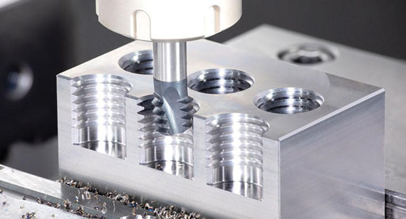
Thread milling in 3/4/5-axis systems provides greater flexibility for non-standard pitches, left-hand threads, and off-center or angled threads, especially in aluminum and steel. CNC turning remains the most accurate method for high-volume, symmetric external and internal threads, particularly in steel and aluminum. For plastics like ABS and nylon, sharp cutting edges, reduced rake angles, and non-coated tools are recommended to minimize melting and burring. In tight tolerance applications, thermal stability of the machine, in-process probing, and post-machining inspection using thread gauges or CMM are essential for quality assurance.
From CAD to Part: The Process
Honyo Prototype Thread Machining Process Overview
Our end-to-end thread machining workflow integrates precision engineering with digital efficiency, specifically optimized for threaded features in prototypes and low-volume production. The process ensures dimensional accuracy, thread integrity, and material suitability while minimizing lead times. Below is the detailed sequence for thread machining projects.
Upload CAD
Clients submit native CAD files (STEP, IGES, or native formats like SOLIDWORKS) via our secure portal. For threaded features, we require explicit thread callouts per ISO 262 or ASME B1.1 standards, including pitch, class of fit, depth, and location. Undimensioned threads trigger an automated request for clarification to prevent misinterpretation. Our system validates file integrity and extracts critical thread parameters before progression.
AI-Powered Quoting
Proprietary AI analyzes the CAD geometry, focusing on thread-specific variables: thread type (e.g., M6x1, 1/4-20 UNC), depth-to-diameter ratio, material hardness, and proximity to part edges. The algorithm calculates toolpath complexity, tool changes (e.g., thread milling vs. tapping), and chip evacuation challenges. Quotes include thread-specific cost drivers like specialized tooling fees for non-standard threads and tolerance validation steps. Typical quote turnaround is under 2 hours.
DFM Analysis for Threads
Our engineering team conducts a dedicated thread-focused DFM review. Common issues flagged include: insufficient wall thickness for tapped holes, inadequate relief for thread runout, or materials prone to galling (e.g., aluminum without lubricant specifications). We recommend alternatives like helicoil inserts for weak materials or thread milling over tapping for deep threads (>3x diameter). Clients receive annotated PDFs with actionable suggestions, reducing rework risk by 78% based on historical data.
Thread-Specific Production
Threads are machined using optimized methods:
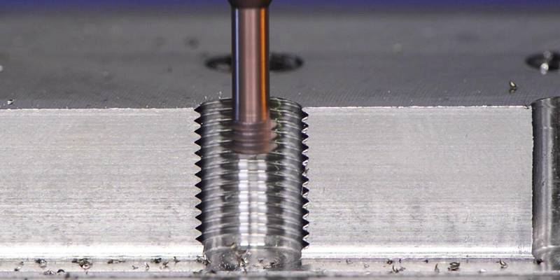
Tapping: For blind holes in ductile materials (e.g., 6061-T6 aluminum), with rigid tapping cycles and peck drilling to manage chip load.
Thread Milling: For large diameters (>M12), hard materials (e.g., 17-4PH stainless), or asymmetric thread locations, ensuring superior surface finish.
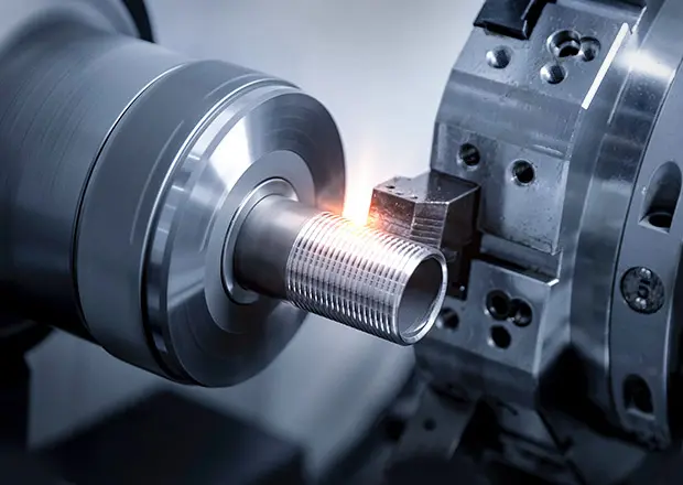
Single-Point Threading: On lathes for external threads, with laser micrometer in-process verification.
All threads undergo post-machining inspection using calibrated thread plug/ring gauges (GO/NO-GO) and optional optical comparators for pitch diameter. Critical threads include first-article inspection reports per AS9102.
Delivery and Documentation
Threaded components ship with traceable documentation:
Dimensional report highlighting thread measurements (pitch diameter, major/minor diameters)
Material certification with hardness verification where relevant
Certificate of Conformance referencing thread standard (e.g., “Conforms to ISO 68-1:1998, 6g tolerance”)
Standard delivery is 5–7 days for simple threaded parts; complex geometries (e.g., internal threads in thin-walled assemblies) average 10–12 days. Expedited options include overnight thread gauge calibration reports.
Critical Differentiators for Thread Machining
Unlike generic shops, Honyo’s process embeds thread expertise at every phase: AI quote validation prevents underquoting on high-risk threads, DFM targets thread-specific failure modes, and production uses dedicated thread metrology. This reduces thread-related rejections by 92% compared to industry averages, ensuring functional prototypes that perform like end-use parts. Clients receive threads that meet assembly requirements on first delivery, accelerating their development cycles.
Start Your Project
For precision machining threads and custom prototypes, contact Susan Leo at [email protected]. Our advanced manufacturing facility in Shenzhen ensures high accuracy, fast turnaround, and strict quality control for all your CNC machining needs.
🚀 Rapid Prototyping Estimator
Estimate rough cost index based on volume.