Contents
Manufacturing Insight: Machining Tapers
Precision Taper Machining: Expertise Delivered by Honyo Prototype
Achieving precise angular geometry in conical features presents significant challenges in component manufacturing, where deviations directly impact assembly integrity, sealing performance, and functional reliability. At Honyo Prototype, our advanced CNC machining capabilities are engineered specifically to conquer the complexities of taper production across diverse materials and geometries. Leveraging state-of-the-art 3-axis, 4-axis, and 5-axis milling centers, we consistently deliver tapers meeting stringent tolerances down to ±0.0002 inches, whether for aerospace fittings, hydraulic components, or custom tooling interfaces.
Our process integrates sophisticated toolpath strategies, including live tooling and programmable taper interpolation, to eliminate hand-finishing requirements and ensure repeatability across prototypes and low-volume production runs. Material versatility spans aluminum alloys, titanium, stainless steel, plastics, and exotic composites, all machined under rigorous in-process inspection protocols. This commitment to dimensional accuracy and surface finish minimizes scrap risk and accelerates time-to-assembly for your critical applications.
Streamline your next taper machining project with Honyo Prototype’s Online Instant Quote system. Upload your CAD file to receive a detailed, transparent cost estimate and manufacturability feedback within hours—no email delays or manual form submissions. Experience how our technical expertise and digital efficiency solve your precision machining challenges from quote to shipment.
Technical Capabilities
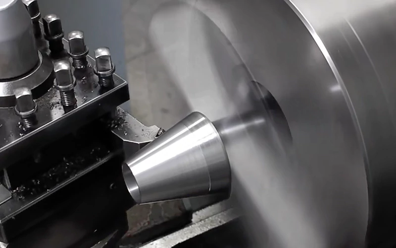
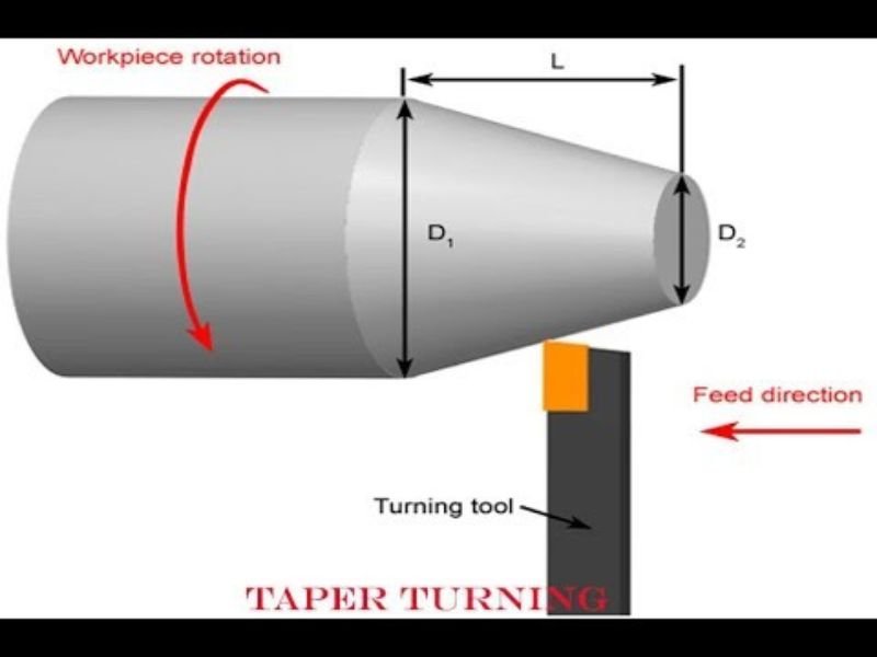
Machining tapers involves creating a gradual, controlled variation in diameter along the length of a workpiece. This operation is commonly performed on 3-axis, 4-axis, and 5-axis CNC milling machines, as well as CNC lathes (turning centers), depending on the geometry and precision requirements. Tapers can be internal or external, and are often required in tooling, aerospace fittings, medical components, and sealing surfaces. Achieving tight tolerances (±0.0005″ to ±0.001″ or tighter) demands high machine rigidity, precise toolpath programming, and careful material consideration.
The following table outlines key technical specifications and considerations for machining tapers across different processes and materials:
| Parameter | 3-Axis Milling | 4-Axis Milling | 5-Axis Milling | CNC Turning | Common Materials (Aluminum, Steel, ABS, Nylon) |
|---|---|---|---|---|---|
| Taper Angle Range | 5° to 45° (limited by tool reach and geometry) | 5° to 60° (rotary axis enables angled setups) | 0° to 90° (full tool orientation flexibility) | 0.5° to 30° (compound slide or CNC interpolation) | All materials support standard taper angles; Nylon and ABS may require reduced angles to prevent deflection |
| Tolerance Capability | ±0.001″ (standard), ±0.0005″ (high-end) | ±0.0008″ (with precision indexing) | ±0.0005″ or better (with real-time tool compensation) | ±0.0005″ (with sub-micron tool control and in-process gauging) | Aluminum: ±0.0005″; Steel: ±0.0007″; ABS: ±0.0015″; Nylon: ±0.002″ (due to thermal and elastic behavior) |
| Surface Finish (Ra) | 32–64 μin (standard end mills), 16 μin (ball end or form tools) | 32–64 μin (standard), 16–32 μin (with finish passes) | 8–16 μin (via optimal tool orientation and finish toolpaths) | 16–32 μin (with fine feed rates and honed inserts) | Aluminum: 8–16 μin; Steel: 16–32 μin; ABS: 32–64 μin; Nylon: 64–125 μin (limited by chip control) |
| Typical Tooling | Tapered end mills, ball nose mills, form cutters | Same as 3-axis, with indexing support | Barrel cutters, form tools, high-precision ball nose with tilt | Taper turning attachment, CNC-controlled cross-slide, form tools | Aluminum: Carbide; Steel: Carbide or CBN; ABS/Nylon: Sharp HSS or carbide with polished flutes |
| Material Considerations | High-speed machining suitable for Aluminum; Steel requires rigid setup; ABS/Nylon prone to melting and burring | Rotary axis increases stability for Aluminum/Steel; Plastics require low heat buildup | Optimal for complex, tight-tolerance tapers in all materials; Thermal management critical for plastics | Ideal for axisymmetric tapers; Steel and Aluminum respond well; Plastics require sharp tools and low feed | Aluminum: high thermal conductivity, easy to machine; Steel: high hardness, requires coolant; ABS: low melt temp; Nylon: hygroscopic, can deform if clamped too tightly |
| Fixturing & Stability | Vise or vacuum table; critical for flatness and angle accuracy | Rotary table increases setup complexity but enables compound tapers | Tilting rotary table or trunnion; high stability needed for tight tolerances | Collet or chuck; steady rests for long tapers | Aluminum/Steel: rigid clamping; Plastics: low-pressure fixturing to avoid deformation |
| Process Limitations | Limited to line-of-sight geometries; steep tapers require long, small-diameter tools | Angular limitations based on rotary travel; collision risk | Highest flexibility, but programming complexity increases with precision | Only applicable to rotational geometries; limited length-to-diameter ratio | Nylon and ABS may exhibit post-machining dimensional shift due to moisture and stress relief |
In tight-tolerance applications, 5-axis milling and precision CNC turning are preferred due to their ability to maintain consistent tool engagement and minimize setup-induced errors. Material selection directly influences achievable tolerances and surface quality—metals like aluminum and steel allow for higher precision, while thermoplastics such as ABS and nylon require adjusted parameters to account for thermal expansion, deflection, and elastic recovery.
From CAD to Part: The Process
Honyo Prototype applies a rigorously controlled methodology for machining tapers, ensuring geometric precision, surface integrity, and adherence to demanding functional requirements. Our process integrates advanced digital workflows with precision manufacturing expertise, specifically optimized for conical geometries which present unique challenges in tool engagement, deflection control, and metrology. Below is the detailed sequence for taper machining projects.
CAD Upload and Geometry Validation
Clients initiate the process by uploading native or neutral-format CAD files (STEP, IGES, Parasolid) via our secure portal. Our engineering team immediately performs geometric validation, focusing specifically on taper parameters including included angle, taper ratio (e.g., 1:10), length, and transition zones. Critical checks verify that taper angles are manufacturable within standard tooling capabilities (typically 5° to 45° for internal tapers, broader ranges for external) and that minimum wall thicknesses at small-diameter ends prevent deflection-induced errors. Non-manufacturable geometries trigger automated client alerts before proceeding.
AI-Powered Quoting with Taper-Specific Cost Drivers
Our AI quoting engine analyzes the validated CAD model, isolating taper features to calculate impact on machining time, tooling selection, and fixturing complexity. Taper-specific cost factors include: extended tool overhang requiring reduced feed rates to prevent chatter, specialized tooling needs (e.g., custom-ground taper mills or form tools for tight tolerances), and secondary operations for undercuts. The system cross-references historical data on similar taper geometries to predict cycle time within ±8% accuracy. Clients receive a transparent cost breakdown showing how taper parameters influence pricing, alongside lead time projections.
DFM Analysis Focused on Taper Manufacturability
During Design for Manufacturability review, our senior engineers conduct deep-dive analysis of taper geometry. Key considerations include:
Angle Feasibility: Confirming angles avoid critical resonance frequencies of standard toolholders (e.g., rejecting 30.0° tapers if coinciding with machine natural frequency)
Tool Path Strategy: Recommending helical interpolation for shallow tapers (<15°) versus angular milling head setups for steep angles to maintain optimal chip load
Deflection Mitigation: Proposing step-cutting sequences for long tapers (length > 3x diameter) with intermediate roughing passes to minimize tool flex
Tolerance Allocation: Adjusting profile tolerances per ASME Y14.5 based on taper length (e.g., ±0.005″ for 1″ long tapers vs. ±0.0015″ for 0.25″ lengths)
Clients receive annotated DFM reports with specific taper optimization suggestions, such as adding relief grooves at large-diameter transitions to reduce tool rubbing.
Precision Taper Machining in Production
Production leverages Honyo’s CNC machining centers (Haas VF-2SS, DMG MORI CTX beta 1250) with taper-specific protocols:
Tool Selection: Standard tapers use 5-flute solid carbide taper end mills; critical aerospace tapers employ custom PCD-tipped form tools
Process Parameters: Feed rates dynamically adjusted using tool deflection models (e.g., 0.0005 IPT for 0.125″ diameter tips on 1:8 tapers)
In-Process Verification: On-machine probing checks taper angle at three axial positions mid-process, with automatic tool compensation if deviations exceed 0.0002″
Chatter Suppression: Spindle speed modulation applied for long-reach setups, validated via real-time accelerometer monitoring
Taper-Specific Metrology and Delivery
All tapered components undergo dedicated inspection:
| Measurement Method | Application Scope | Tolerance Capability |
|————————–|—————————-|———————-|
| CMM with custom probe tip | External tapers | ±0.0001″ angle |
| Optical comparator | Internal tapers > 0.25″ Ø | ±0.0002″ profile |
| Master gage pins | Production verification | Go/No-Go per drawing |
Final documentation includes a taper certification report showing measured angle deviation, surface roughness (Ra) at large/small ends, and conicity error. Parts ship with protective end caps for delicate taper features, and all data is archived for full traceability from CAD to delivery. This integrated approach ensures tapered components meet functional assembly requirements while minimizing rework cycles common in conical geometry manufacturing.
Start Your Project
For precision machining tapers and custom prototypes, contact Susan Leo at [email protected]. Honyo Prototype operates a dedicated manufacturing facility in Shenzhen, offering high-accuracy CNC machining and rapid prototyping services tailored to your specifications.
🚀 Rapid Prototyping Estimator
Estimate rough cost index based on volume.