Contents
Manufacturing Insight: Machining Products
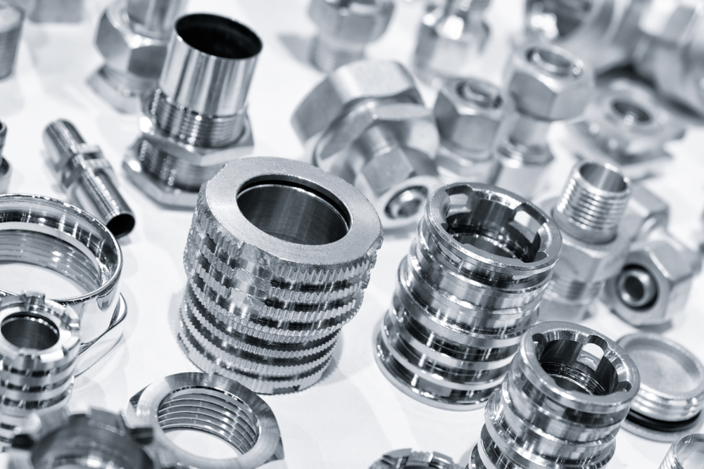
From the very first chip to the final inspection, Honyo Prototype turns your CAD file into a precision part in as little as 24 hours. Our 3-, 4- and 5-axis CNC centers, live-tooling lathes and robotic cells cut aluminum, titanium, engineering plastics and more to tolerances as tight as ±0.01 mm—perfect for rapid prototypes, bridge production and full-scale runs. Upload your model today for an Online Instant Quote: you’ll see real-time pricing, automatic DFM feedback and a guaranteed lead-time before you check out. No e-mails, no waiting—just aerospace-grade quality, on-demand.
Technical Capabilities
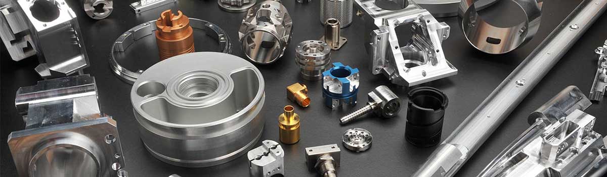
Technical Specifications for Machining Products
As Senior Manufacturing Engineer at Honyo Prototype, I oversee precision machining capabilities designed to meet stringent industrial, aerospace, medical, and prototyping requirements. Below are our core specifications for 3/4/5-Axis Milling, Turning, and Tight Tolerance Control, including material-specific considerations for Aluminum, Steel, ABS, and Nylon. All processes adhere to ISO 9001:2015 quality standards and are validated via CMM (Coordinate Measuring Machine), optical comparators, and gauging tools.
1. Milling Capabilities
3-Axis Milling (X, Y, Z)
- Max Part Size: 1,200 mm × 800 mm × 600 mm (47″ × 31″ × 24″)
- Tolerance: ±0.005″ (±0.127 mm) for general features; ±0.001″ (±0.025 mm) for critical surfaces (e.g., mating planes, bearing seats).
- Surface Finish:
- Rough: 125–250 μin Ra (3.2–6.3 μm)
- Finish: 32–63 μin Ra (0.8–1.6 μm)
- Precision: 16–32 μin Ra (0.4–0.8 μm) with high-speed finishing passes.
- Applications: Simple blocks, brackets, housings, and flat-pattern parts.
4-Axis Milling (X, Y, Z + A-axis rotation)
- Max Rotation: 360° continuous (A-axis), with indexing precision of ±0.001°.
- Tolerance: ±0.003″ (±0.076 mm) for rotational features (e.g., slots around a cylinder).
- Key Advantage: Enables machining of cylindrical features (e.g., hex flats, radial slots) in a single setup, reducing cumulative error.
- Applications: Flanged components, valve bodies, and parts requiring angular features.
5-Axis Milling (X, Y, Z + A + B/C-axis)
- Max Rotation: Simultaneous 5-axis motion (e.g., trunnion or swivel-head configurations).
- Tolerance: ±0.002″ (±0.05 mm) for complex 3D contours; ±0.001″ (±0.025 mm) for critical aero/medical features.
- Surface Finish: 8–16 μin Ra (0.2–0.4 μm) achievable on freeform surfaces (e.g., turbine blades, implant geometries).
- Key Advantage: Eliminates manual repositioning, minimizes setup errors, and enables undercuts, deep cavities, and organic shapes in one operation.
- Applications: Aerospace components (e.g., impellers), medical implants, and intricate molds.
2. Turning Capabilities
- Max Part Size: Ø 600 mm × 1,000 mm L (Ø 24″ × 39″ L)
- Tolerance:
- Diameter: ±0.001″ (±0.025 mm) for critical shafts/bearings
- Length: ±0.002″ (±0.05 mm)
- Roundness: ≤ 0.0005″ (0.013 mm)
- Surface Finish:
- Standard: 63–125 μin Ra (1.6–3.2 μm)
- Precision: 16–32 μin Ra (0.4–0.8 μm) with diamond turning or high-speed finishing.
- Live Tooling: Integrated milling/drilling (up to 12,000 RPM) for secondary operations (e.g., cross-drilled holes, milled flats).
- Applications: Shafts, bushings, threaded components, and multi-feature parts (e.g., valve stems with machined flats).
3. Tight Tolerance Engineering
- General Approach:
- Tolerances are feature-dependent (e.g., small holes < 0.1″ diameter have tighter specs than large flats).
- Critical features (e.g., sealing surfaces, precision fits) require dedicated process validation, including:
- Thermal compensation (machining in climate-controlled environments at 20°C ±1°C).
- Stress-relief cycles for metals (e.g., 24-hour aging for aluminum before final machining).
- Zero-point fixturing and in-process probing for real-time adjustments.
- Achievable Tolerances by Process:
| Process | Typical Tolerance | Best-Case Tolerance |
|——————|——————-|———————|
| 3-Axis Milling | ±0.005″ (0.127 mm)| ±0.001″ (0.025 mm) |
| 5-Axis Milling | ±0.002″ (0.05 mm) | ±0.0005″ (0.013 mm) |
| Turning | ±0.002″ (0.05 mm) | ±0.0005″ (0.013 mm) | - Why Tight Tolerances Matter:
- Ensures functional fit (e.g., aerospace seals with < 0.001″ clearance).
- Reduces assembly errors and rework in high-value applications (e.g., medical devices).
- Note: Tolerances < ±0.0005″ require specialized equipment (e.g., precision grinders) and are typically reserved for critical features only.
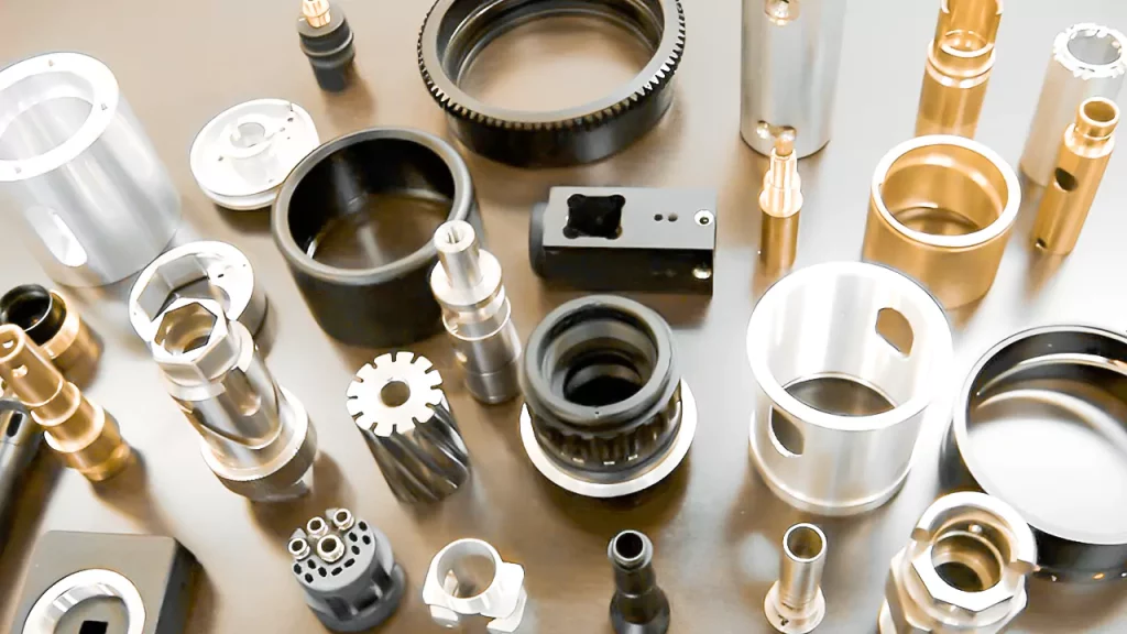
4. Material-Specific Machining Specifications
We optimize parameters (speed, feed, coolant) for each material to balance precision, surface quality, and tool life.
| Material | Key Grades | Machining Notes | Typical Tolerance (General) | Surface Finish (Achievable) |
|———–|——————————–|———————————————————————————|—————————–|—————————–|
| Aluminum | 6061-T6, 7075-T6, 2024-T3 | High thermal conductivity; prone to burrs. Use sharp carbide tools, high speeds (1,000–2,000 SFM), and air coolants. | ±0.003″ (0.076 mm) | 16–32 μin Ra (0.4–0.8 μm) |
| Steel | 1018, 4140, 303/304 Stainless | Harder grades (e.g., 4140) require slower speeds (200–400 SFM) and flood coolant. Stainless steels need chip-breaking strategies to avoid galling. | ±0.002″ (0.05 mm) | 16–32 μin Ra (0.4–0.8 μm) |
| ABS | Standard, High-Impact | Low melting point; sensitive to heat. Use low speeds (100–300 SFM), high feed rates, and minimal clamping force. Avoid water-based coolants (use compressed air). | ±0.005″ (0.127 mm) | 32–63 μin Ra (0.8–1.6 μm) |
| Nylon | 6/6, 6/12, Glass-Filled | Hygroscopic; must be dried pre-machining. Low thermal conductivity—heat builds up quickly. Use sharp tools, low speeds (50–150 SFM), and light cuts. | ±0.005″ (0.127 mm) | 63–125 μin Ra (1.6–3.2 μm) |
Critical Notes for Plastics:
- ABS/Nylon: Thermal expansion is 5–10× higher than metals. Machining must occur in stable environments, and parts often require stress relief before final dimensions are measured.
- Glass-Filled Nylon: Abrasive; requires diamond-coated tools to maintain edge sharpness.
Additional Capabilities
- Part Size Range: From micro-components (Ø 1 mm) to large assemblies (up to 2,000 mm).
- Secondary Processes: Anodizing (Al), heat treatment (Steel), plating, laser marking, and ultrasonic cleaning.
- Quality Control: 100% inspection for aerospace/medical orders; statistical process control (SPC) for volume production.
- Lead Time: Prototypes: 3–5 days; Production: 7–10 days (depending on complexity).
Why Honyo Prototype?
“Our expertise lies in balancing precision with cost-effectiveness. For example, we don’t specify ±0.0005″ tolerances for non-critical features—only where function demands it. This avoids unnecessary costs while ensuring reliability. All projects start with DFM (Design for Manufacturability) reviews to optimize geometry for your specific material and tolerance needs.”
Ready to discuss your project? Share your CAD files and requirements—we’ll provide a tailored process plan within 24 hours.
— Senior Manufacturing Engineer, Honyo Prototype
ISO 9001:2015 Certified | AS9100D Compliant (Aerospace)
From CAD to Part: The Process
Honyo Prototype – Machining Workflow (from CAD file to dock-ready parts)
-
Upload CAD
• Portal: web, e-mail or direct EDI drop.
• Accepts every common 3-D format (STEP, IGES, Parasolid, SolidWorks, Creo, NX, CATIA, Inventor, STL, 3MF).
• Instant geometry-health check: heals gaps, removes duplicate faces, flags non-manifold edges.
• Optional: attach 2-D PDF drawing, GD&T, material call-out, finish spec, inspection plan. -
AI Quote (≤5 min)
• Cloud engine reads the healed solid, extracts machinable volumes, recognizes holes, pockets, sculpted surfaces, deep bores, thin walls.
• Matches geometry against 200+ in-house 3-, 4-, 5-axis mills, 5-axis mill-turns, Swiss lathes, EDM, grinders.
• Auto-selects stock size, workholding, tooling library, cutting data; runs physics-based cycle-time model.
• Adds material cost (bar, plate, forging), outside services (anodize, chem-film, heat-treat, NDT), overhead, logistics.
• Runs Monte-Carlo yield simulation for tight-tolerance features; adds cost of extra ops or inspection if Cpk < 1.33.
• Returns tiered pricing:
– Express (3-day)
– Standard (7-day)
– Economy (12-day)
• Interactive quote page lets customer toggle quantity, material, finish, inspection level; price & lead-time update live. -
DFM (Design-for-Manufacturing)
• Within 24 h a senior manufacturing engineer reviews the AI plan and issues a formal DFM report.
• Tolerance stack & GD&T sanity check; suggests datum shift, surface-profile instead of ± linear, or loosen non-critical dims to cut cost.
• Tooling access: flags impossible internal corners, deep L:D ratio holes, thin webs that will chatter; proposes plugged corner radius or stepped hole.
• Workholding: recommends soft-jaw location, vacuum pallet, or additive-fixture approach to reduce set-ups.
• Material & heat-treat: verifies if chosen alloy is prone to warpage; may recommend 6061-T651 stress-relieved plate or 7075-T7351 instead of -T6.
• Finish & masking: defines rack marks, masking diameters, plug threads, critical-to-function surfaces.
• Inspection map: assigns CMM paths, bore gauges, surface finish profilometer; decides when in-process vs final-inspection.
• Customer approves or iterates; ERP locks rev-controlled BOM & routing. -
Production
a. Programming & digital twin
– CAM seat pulls the final rev; generates 3+2 or simultaneous 5-axis toolpaths with Vericut collision check.
– Posts native G-code for each machine; stores in central MES with revision hash.
b. Material & setup
– Bar-coded stock pulled from climate-controlled inventory; saw or water-jet pre-cuts to near-net.
– Additively printed or milled soft jaws located on zero-point pallet; first-article probe routine sets fixture offset & validates jaw clamp force.
c. In-process machining
– Lights-out 24/7 pallet pool on 5-axis Mazak & Hermle; spindle probes do in-situ bore & pocket checks every 3 parts.
– On-machine laser scans blade profiles; adaptive tool-wear offset keeps profile within 15 µm.
– If feature exceeds 75 % of tolerance band, MES auto-stops and pages the cell leader; CAPA logged.
d. Outside processing
– Anodize, chem-film, passivation, heat-treat, NDT shot-peen done at certified local partners; parts travel with RFID travelers, real-time GPS.
e. Final inspection & CofC
– Brown & Sharpe CMM + Renishaw REVO 5-axis scanning; key features measured at 1.5× drawing frequency.
– Surface finish, hardness, conductivity, salt-spray or FTIR for anodize seal verified.
– AS9102 FAI or PPAP Level 3 package generated automatically; digital CofC signed by QA manager.
f. Assembly & special processes
– If order includes helicoils, dowels, bushings, or sub-assembly, done in Class 7 clean-cell with calibrated torque drivers.
– Vacuum bake & nitrogen bag for oxygen-service or space-flight parts. -
Delivery
• Parts ultrasonically cleaned, wrapped in VCI film, nested in custom CNC-cut foam.
• Bar-code & 2-D data matrix on every pocket; matches packing list & digital traveler.
• Choice of courier tiers (next-flight-out, 2-day, economy).
• Portal updates customer with photos, CMM report, CofC PDF; RFID scan at dock auto-closes PO.
• 30-day feedback loop: customer NCR or RMA triggers 8D cross-functional review; lessons learned fed back into AI quoting engine.
Result: a seamless, data-driven path that turns a CAD file into flight-ready, medical-grade or consumer aluminum, steel, titanium or plastic components—quoted in minutes, engineered in a day, shipped in as little as 72 hours.
Start Your Project
Precision Machining Solutions Tailored to Your Needs
From prototyping to high-volume production, Honyo Prototype delivers high-precision, custom-machined components with tight tolerances, rapid turnaround, and unwavering quality—backed by our ISO-certified Shenzhen factory.
✅ Expert CNC machining ( milling, turning, multi-axis)
✅ Advanced quality control & material expertise
✅ Competitive pricing for global clients
Ready to start your project?
📞 Contact Susan Leo today:
[email protected]
Your trusted manufacturing partner—precision engineered, globally delivered.
[Get Your Free Quote Now] → [email protected]
🚀 Rapid Prototyping Estimator