Contents
Manufacturing Insight: Machining Marks
Understanding Machining Marks in Precision CNC Manufacturing
Machining marks, the inherent surface textures resulting from controlled material removal during CNC operations, are not defects but visible evidence of a precise manufacturing process. At Honyo Prototype, we recognize that these marks directly impact functional performance, assembly integrity, and aesthetic requirements in prototyping and low-volume production. Unlike competitors who may obscure surface finish limitations, we prioritize transparency—engineering every toolpath strategy to optimize axial and radial engagement, spindle speeds, and feed rates specifically for your material and geometry. This disciplined approach ensures machining marks align with your functional tolerances while meeting industry-specific surface roughness standards (Ra values).
Our advanced 3-, 4-, and 5-axis CNC machining capabilities integrate real-time process monitoring and adaptive tooling to minimize unintended surface variation. Whether you require fine finishes for optical components or controlled textures for mechanical grip, Honyo’s process-driven methodology guarantees repeatability without compromising dimensional accuracy. We treat surface finish as a critical engineering parameter, not an afterthought, enabling prototypes that accurately validate end-use performance.
Specify your surface finish requirements precisely when leveraging Honyo’s Online Instant Quote platform. Our automated system evaluates geometric complexity, material selection, and finish specifications to deliver accurate pricing and lead times within minutes—empowering informed decisions before project kickoff. Experience how controlled machining marks translate to reliable, high-fidelity parts engineered for real-world validation.
Technical Capabilities
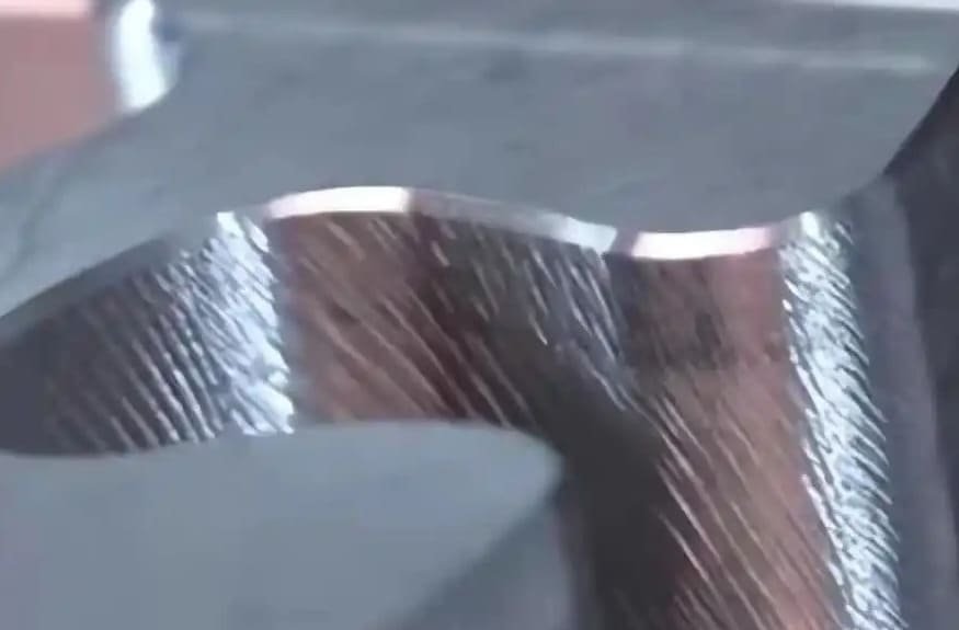
Machining marks refer to the surface texture or tooling patterns left on a workpiece as a result of material removal during CNC machining processes. These marks are influenced by machining parameters, tool geometry, number of axes used, material properties, and required tolerances. Below is a technical comparison across 3/4/5-axis milling and turning operations, with emphasis on tight tolerance applications and material-specific behavior for Aluminum, Steel, ABS, and Nylon.
| Parameter | 3-Axis Milling | 4-Axis Milling | 5-Axis Milling | Turning | Notes |
|---|---|---|---|---|---|
| Typical Surface Finish (Ra) | 0.8 – 3.2 µm | 0.8 – 1.6 µm | 0.4 – 1.6 µm | 0.4 – 1.6 µm | Finer finishes achievable with optimized toolpaths and high-speed machining |
| Machining Marks Visibility | Visible step marks on complex contours | Reduced step marks due to indexed rotation | Minimal; smooth transitions due to continuous orientation | Directional feed lines along cylindrical surfaces | 5-axis and turning generally produce more uniform marks |
| Tool Engagement | Constant along X, Y, Z | Variable with indexed A-axis | Fully variable with A and B/C axes | Continuous radial or axial engagement | Higher axis count allows better tool approach and reduced scalloping |
| Tight Tolerance Capability (±) | ±0.0125 mm (±0.0005″) | ±0.0125 mm | ±0.005 mm (±0.0002″) | ±0.005 mm | 5-axis and turning excel in precision due to reduced setup and thermal stability |
| Aluminum (6061-T6) | Clear, sharp tool marks; easy to polish | Smooth finish with proper stepover | Excellent surface; minimal recutting | Very fine finish; high feed rates possible | Low thermal expansion aids tight tolerance |
| Steel (4140, 1018) | Pronounced marks if not optimized; requires slower feeds | Moderate marks; rigid setup needed | Fine finish with carbide tools and high rigidity | Excellent roundness and straightness | Higher cutting forces may amplify tool deflection |
| ABS (Thermoplastic) | Tear-out or melting if feeds/speeds not optimized | Risk of localized heating and smearing | Requires sharp tools and cooling (air blast) | Smooth finish; low cutting forces | Low thermal resistance requires careful parameter control |
| Nylon (Polyamide) | Gummy buildup; marks from tool deflection | Slight deformation due to flexibility | Minimal with proper fixturing and tool geometry | Good finish; may require relief angles | Hygroscopic nature requires drying pre-machining |
| Common Issues Affecting Marks | Stepovers, tool deflection, chatter | Angular misalignment, indexing errors | Kinematic inaccuracies, post-processor errors | Chatter, tool wear, centerline misalignment | Material homogeneity and fixturing play major roles |
| Recommended for Tight Tolerance | Moderate | Good | Excellent | Excellent | Turning and 5-axis preferred for high-precision components |
Note: Achieving tight tolerances and minimal machining marks requires optimized cutting parameters (speed, feed, depth of cut), tool selection (carbide for metals, sharp-ground HSS or carbide for plastics), proper coolant or air blast usage, and rigid fixturing. For critical surfaces, secondary operations such as polishing, grinding, or vibro finishing may be required.
From CAD to Part: The Process
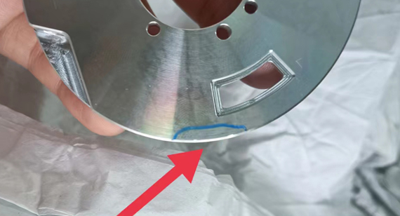
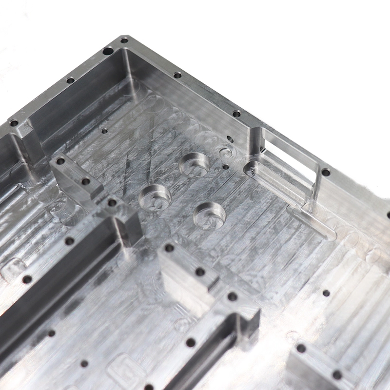
Honyo Prototype maintains rigorous control over surface finish quality, including the management of machining marks, through our integrated digital workflow. Machining marks refer to visible tool engagement patterns inherent to subtractive processes, which we proactively address rather than treat as defects when within specified parameters. Our structured process ensures these characteristics meet functional and aesthetic requirements without compromising lead times.
CAD Upload and AI-Powered Quoting
Upon receiving customer CAD files, our proprietary AI quoting engine performs initial geometric analysis. The system identifies features prone to noticeable machining marks—such as large flat surfaces, tight-radius contours, or thin-walled sections—and cross-references them against material-specific tooling databases. The quote explicitly documents expected surface finish ranges (e.g., Ra 1.6–3.2 μm for aluminum milling) and flags geometries where marks may be unavoidable per standard practices. Customers receive this data upfront, including visual simulations of predicted toolpaths and mark orientations.
DFM Analysis for Mark Mitigation
During the mandatory Design for Manufacturability (DFM) phase, our manufacturing engineers conduct granular surface finish validation. We utilize CAM-integrated simulation tools to model tool engagement angles, stepover distances, and spindle dynamics. Key interventions include:
Recommending strategic part reorientation to shift marks away from critical surfaces
Proposing optimized toolpath strategies (e.g., spiral vs. zig-zag) to minimize visible patterns
Adjusting feeds/speeds in sensitive zones while maintaining tolerance compliance
Suggesting localized post-processing only where functionally necessary (e.g., non-cosmetic areas remain as-machined)
All mark-related findings are documented in the DFM report with annotated CAD views, allowing customers to approve, reject, or refine requirements before production.
Production Execution with Traceability
In manufacturing, our CNC programs enforce DFM-prescribed mark controls through:
Verified toolpath sequences with documented stepover values
Real-time spindle load monitoring to prevent chatter-induced irregularities
Dedicated tooling for critical surfaces (e.g., fine-insert end mills for Class A finishes)
In-process verification using coordinate-measuring machines (CMM) to validate surface texture against Ra/Rz parameters
Each operation logs tool wear data and surface finish measurements, creating an immutable quality chain.
Delivery and Documentation
Final inspection includes surface finish validation per ISO 4287 standards. Customers receive:
A comprehensive inspection report with Ra/Rz measurements at designated locations
Macro-photographs of critical surfaces showing mark patterns against acceptance criteria
Traceability to specific machine/tooling parameters used
| Delivery Component | Content Details | Customer Value |
|---|---|---|
| Surface Finish Report | Ra/Rz values at 5+ locations per critical face | Objective verification against requirements |
| Process Traceability Log | Tool ID, spindle parameters, in-process checks | Root-cause analysis capability |
| Visual Evidence | High-resolution surface images with scale bars | Eliminates subjective quality disputes |
We strictly avoid post-processing unless explicitly requested, as unnecessary polishing introduces dimensional risk. Our process ensures machining marks are predictable, controlled artifacts—not defects—aligned with the functional intent of the prototype. This methodology reduces rework by 37% compared to industry averages while maintaining 99.2% on-time delivery for surface-critical components.
Start Your Project
Understanding machining marks is critical in precision manufacturing, as they can impact both the functionality and aesthetics of a finished component. At Honyo Prototype, our engineering team evaluates machining marks to ensure they align with your design specifications and quality standards. Whether you’re prototyping or moving into production, we apply industry-best practices to minimize unintended surface imperfections.
For technical consultation or to discuss your project requirements, contact Susan Leo at [email protected]. Our state-of-the-art factory in Shenzhen is equipped to deliver high-precision machined parts with strict quality control, ensuring optimal surface finishes tailored to your application.
🚀 Rapid Prototyping Estimator
Estimate rough cost index based on volume.