Contents
Manufacturing Insight: Machining Finish Symbols
Understanding Machining Finish Symbols for Precision CNC Manufacturing
Surface texture specifications, defined through standardized machining finish symbols per ISO 1302 or ASME Y14.36M, are critical technical requirements that directly impact a component’s functionality, fatigue resistance, sealing integrity, and wear performance. These symbols communicate precise manufacturing instructions beyond dimensional tolerances, dictating the allowable surface roughness (Ra, Rz), waviness, lay direction, and production method. Misinterpretation or inconsistent application of these parameters can lead to part failure, assembly issues, or accelerated degradation in precision-critical applications such as aerospace hydraulics, medical implants, or semiconductor tooling.
At Honyo Prototype, our CNC machining expertise ensures these specifications are rigorously implemented across milling, turning, and multi-axis operations. Our engineering team collaborates directly with your design intent, translating surface finish symbols into optimized toolpaths, cutting parameters, and post-process validation using calibrated profilometers. We maintain strict adherence to ISO 2768 and customer-specific surface quality protocols, guaranteeing that every machined component meets the functional and aesthetic criteria defined in your technical documentation. This precision eliminates costly rework and accelerates time-to-market for prototypes and low-volume production runs.
Leverage our technical proficiency with Honyo’s Online Instant Quote platform. Simply upload your STEP or DWG file with complete geometric dimensioning and surface finish annotations to receive an accurate, detailed manufacturing assessment and competitive pricing within hours—not days. Start your project with confidence by ensuring surface requirements are manufactured correctly from the first iteration.
Technical Capabilities
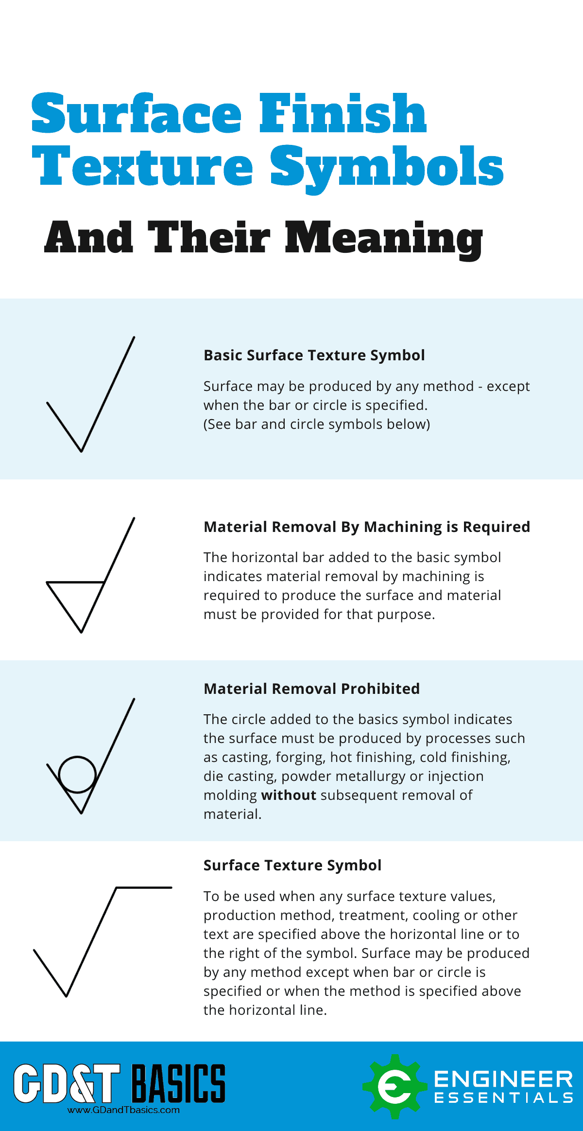
Machining finish symbols are standardized notations used on engineering drawings to specify surface texture requirements for machined components. These symbols convey critical information such as surface roughness (Ra), machining method, lay direction, and any additional processing notes. In high-precision manufacturing environments involving 3-axis, 4-axis, and 5-axis milling, as well as CNC turning, these symbols ensure consistent quality, especially when tight tolerances (e.g., ±0.0005″ or ±0.0127 mm) are required.
The following table outlines typical technical specifications associated with machining finish symbols across common manufacturing processes and materials:
| Parameter | 3/4/5-Axis Milling | CNC Turning | Surface Roughness (Ra) Range | Material Considerations |
|---|---|---|---|---|
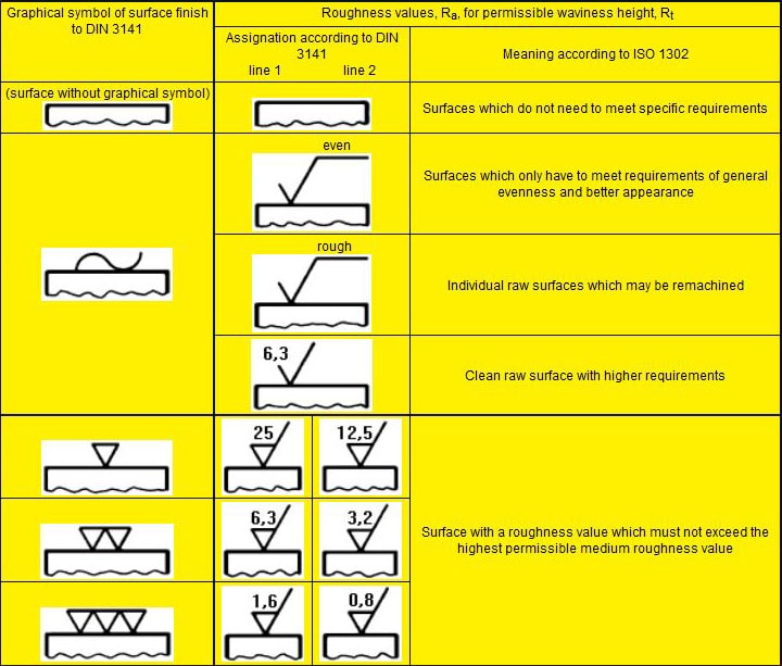
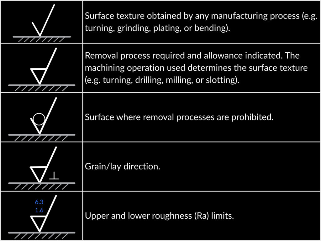
| Typical Machining Finish Symbol | Indicates roughness value (Ra), machining method (e.g., milling), and optional lay pattern (e.g., parallel, multidirectional) | Specifies Ra, tool type, and direction of lay (e.g., circular) | 0.8–3.2 µm (32–125 µin) standard; down to 0.4 µm (16 µin) for fine finishes | Varies significantly by material group |
| Standard Ra for Tight Tolerance Work | 0.8 µm (32 µin) typical; 0.4 µm (16 µin) achievable with fine toolpaths and low stepovers | 0.8 µm (32 µin) typical; 0.2–0.4 µm (8–16 µin) with fine turning or skiving | 0.2–1.6 µm (8–63 µin) depending on process and tool condition | Critical for sealing, mating, or dynamic surfaces |
| Aluminum (e.g., 6061-T6, 7075-T6) | Easily achieves Ra 0.8 µm with carbide end mills; polished finishes down to Ra 0.2 µm possible | Excellent surface finish; Ra 0.4–0.8 µm standard with sharp inserts | 0.4–1.6 µm typical | Low cutting forces; high thermal conductivity; prone to smearing if tools are dull |
| Steel (e.g., 4140, 1018, Stainless 303/316) | Requires rigid setup; Ra 0.8–1.6 µm standard; fine milling can reach Ra 0.4 µm | Ra 0.8 µm standard; harder steels may require wiper inserts for finer finish | 0.8–3.2 µm typical; down to 0.4 µm with precision tooling | Higher tool wear; coolant/lubrication critical; surface integrity affects fatigue life |
| ABS (Thermoplastic) | Machinable with sharp tools; Ra 1.6–3.2 µm typical; prone to melting if feeds/speeds incorrect | Possible but less common; Ra 3.2 µm typical due to material softness | 1.6–6.3 µm typical | Low melting point; chip evacuation important; static buildup possible |
| Nylon (Polyamide, e.g., PA6, PA66) | Tends to deform; Ra 3.2 µm typical; use of sharp, polished tools recommended | Ra 3.2–6.3 µm typical; material compliance affects finish consistency | 3.2–6.3 µm typical | High elasticity; low thermal conductivity; requires minimal cutting pressure |
Additional Notes:
Machining finish symbols may include removal process indicators (e.g., “C” for chip removal) or “no removal” (circle on symbol) for as-cast or forged surfaces.
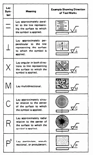
In multi-axis milling, the lay direction (indicated in the symbol) must align with toolpath strategy to avoid crosshatch or unintended texture.
For tight tolerance components, surface finish directly impacts fit, function, and sealing performance—especially in hydraulic, aerospace, and medical applications.
When specifying finishes on drawings, ASME Y14.36M or ISO 1302 standards are typically followed, depending on regional or industry requirements.
From CAD to Part: The Process
Honyo Prototype’s process for manufacturing components with specified surface finishes follows a rigorous, integrated workflow designed to ensure precision and compliance with engineering requirements. It is critical to clarify that “machining finish symbols” refer to the interpretation and execution of surface finish specifications (e.g., Ra values, machining marks, or geometric tolerances annotated in CAD models), not the physical machining of symbolic characters. Below is a technical breakdown of our stage-by-stage methodology:
CAD Upload and Specification Extraction
Upon receiving the customer’s 3D CAD model (STEP, IGES, or native formats), our system parses all geometric dimensioning and tolerancing (GD&T) data, including surface finish callouts. Annotations such as Ra 1.6µm, N6 roughness, or specific machining patterns are isolated and cross-referenced against the model geometry. Non-standard symbols or ambiguous annotations trigger an immediate engineering review request before proceeding, ensuring no misinterpretation of critical finish requirements.
AI-Powered Quoting with Finish Validation
Our proprietary AI quoting engine evaluates surface finish specifications alongside material, geometry, and volume. The system references an internal database of historical machining parameters to assess feasibility and cost impact. For example, achieving Ra 0.4µm on aluminum 6061 versus Ra 0.8µm on stainless steel 316L requires distinct toolpath strategies and secondary operations, which the AI quantifies in lead time and cost. Unattainable finishes (e.g., Ra 0.2µm via milling alone without polishing) are flagged with technical alternatives in the quote.
Engineering-Led DFM Analysis for Surface Integrity
During Design for Manufacturability (DFM) review, our manufacturing engineers validate surface finish requirements against practical machining constraints. Key considerations include:
Tool access limitations affecting roughness in deep pockets
Material properties influencing achievable Ra values (e.g., castings vs. wrought alloys)
Conflicts between adjacent finish specs (e.g., a mirror finish next to a knurled surface)
Cost-optimal process sequencing (e.g., grinding vs. precision milling for flatness)
Customers receive a formal DFM report with actionable recommendations, such as relaxing non-critical finishes to reduce costs by 15–30% without compromising function.
Precision Production with Finish-Centric Process Control
Surface finish execution is governed by documented work instructions derived from DFM outcomes. Critical parameters are controlled as follows:
| Finish Requirement | Typical Process | Key Control Parameters | Verification Method |
|---|---|---|---|
| Ra 3.2–6.3µm | Milling/turning | Feed rate, cutter geometry, coolant | Portable profilometer |
| Ra 0.8–1.6µm | Precision milling/grinding | Spindle speed, stepover, tool wear | Lab-based roughness tester |
| Ra < 0.4µm | Polishing/honing | Abrasive grade, pressure, time | Optical interferometry |
All finishing operations undergo real-time monitoring via IoT-enabled machine tools, with first-article inspection validating compliance against the CAD-specified callouts before batch production.
Delivery with Traceable Finish Certification
Final inspection includes surface roughness validation at multiple locations per ASME B46.1 standards. Results are documented in the Coordinated Inspection Report (CIR), which correlates measured Ra values to specific CAD surfaces. For mission-critical applications (e.g., aerospace or medical), we provide full traceability from raw material to finished part, including tool calibration records and environmental conditions during finishing. Parts ship with protective packaging to prevent finish degradation during transit, and digital as-built reports are accessible via our customer portal.
This closed-loop process ensures surface finish requirements are not merely translated but engineered into the part through validated manufacturing science, eliminating ambiguity between design intent and physical realization. Honyo’s integration of AI-driven feasibility analysis with human engineering oversight guarantees that finish specifications directly translate to functional performance in the final assembly.
Start Your Project
For detailed guidance on machining finish symbols and surface finish requirements, contact Susan Leo at [email protected]. Our engineering team in Shenzhen is equipped to support your precision manufacturing needs with clear, standardized finish specifications.
All parts are produced in our Shenzhen factory, where strict quality control ensures compliance with international surface finish standards.
Reach out today to request technical documentation or to discuss your project requirements.
🚀 Rapid Prototyping Estimator
Estimate rough cost index based on volume.