Contents
Manufacturing Insight: Machining Fillet
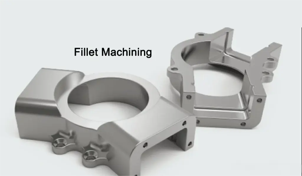
Precision Fillet Machining: Engineering Strength and Flow into Every Component
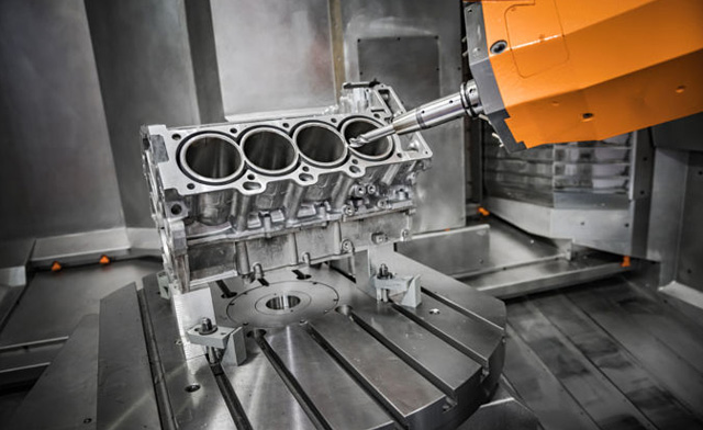
At Honyo Prototype, fillet machining represents far more than a simple radius application—it is a critical engineering intervention that directly impacts part integrity, fatigue life, and functional performance. Poorly executed fillets introduce stress concentrations that become failure initiation points, while precision-machined transitions distribute loads evenly, enhance aesthetic quality, and ensure seamless assembly. Our advanced CNC milling and turning capabilities, driven by multi-axis machining centers and rigorous process validation, transform this essential feature from a potential weakness into a hallmark of component reliability. We specialize in generating consistent, burr-free internal and external fillets across complex geometries and challenging materials—from aerospace alloys to medical-grade polymers—using optimized toolpath strategies and micro-precision tooling to achieve exact radii down to ±0.05mm tolerances.
This technical precision is foundational to Honyo’s broader CNC machining service suite, where every operation undergoes systematic validation against AS9100 and ISO 9001 standards. Whether integrating fillets into high-tolerance hydraulic manifolds, ergonomic medical housings, or structural aerospace brackets, our engineers prioritize manufacturability without compromising design intent. Material-specific parameters, adaptive cutting techniques, and in-process inspection guarantee that fillet surfaces meet stringent Ra 0.8µm finish requirements while eliminating micro-cracks or tool marks that compromise performance.
To accelerate your path from design to certified prototype or production part, leverage Honyo’s Online Instant Quote platform. Upload your STEP or IGES file to receive a detailed manufacturability analysis and competitive pricing within hours—no manual back-and-forth required. This transparency ensures your fillet-critical components are quoted accurately against real-world machining constraints, empowering faster validation cycles and time-to-market.
Fillet Type Application Examples
| Fillet Type | Typical Application | Honyo Process Focus |
|——————-|—————————————–|—————————————–|
| Internal Radius | Mold cavities, bracket junctions | Corner engagement control, chip evacuation |
| External Radius | Shaft shoulders, ergonomic handles | Surface finish consistency, edge blending |
| Variable Radius | Aerodynamic surfaces, organic forms | 5-axis contouring, dynamic tool compensation |
Technical Capabilities
Technical specifications for machining fillets involve precise control of toolpath geometry, tool selection, and machine capability to achieve consistent radii on part edges. Fillets are typically machined using end mills with corner radii or ball-nose cutters in 3, 4, or 5-axis milling, and with CNC turning using radius tools or interpolated paths. Tight tolerance fillets require high-precision tooling, rigid setups, and process stability to maintain geometric accuracy and surface finish.
Below is a summary of technical considerations for machining fillets across different manufacturing processes and materials:
| Parameter | 3-Axis Milling | 4-Axis Milling | 5-Axis Milling | CNC Turning | Tight Tolerance Capability |
|---|---|---|---|---|---|
| Typical Tools Used | Corner radius end mills, ball-nose end mills | Same as 3-axis, with rotary indexing | Ball-nose or radius end mills with continuous 5-axis toolpath | Radius-turning tools, CBN or carbide inserts | Polished carbide, diamond-coated tools |
| Fillet Radius Range | 0.2 mm – 12 mm | 0.2 mm – 12 mm | 0.1 mm – 12 mm | 0.4 mm – 25 mm | 0.05 mm – 6 mm (tight tolerance) |
| Typical Tolerance | ±0.1 mm | ±0.08 mm | ±0.05 mm | ±0.05 mm | ±0.01 mm to ±0.025 mm |
| Surface Finish (Ra) | 1.6 – 3.2 µm | 1.6 – 2.4 µm | 0.8 – 1.6 µm | 0.8 – 1.6 µm | <0.8 µm (with polishing or fine stepover) |
| Material Compatibility | Aluminum, Steel, ABS, Nylon | Aluminum, Steel, ABS, Nylon | Aluminum, Steel, ABS, Nylon | Aluminum, Steel | Aluminum, Steel (Nylon/ABS limited) |
| Aluminum Machinability | Excellent; high feed rates, coolant recommended | Good; improved access with indexing | Excellent; complex fillets possible | Excellent; sharp tools for burr control | Achievable with stable spindle and tooling |
| Steel Machinability | Good; harder grades require carbide tools | Moderate; slower speeds, rigid setup | Good; reduced tool engagement | Good; CBN tools for hardened steel | Challenging; requires thermal stability |
| ABS Machinability | Fair; low melting point, chip evacuation critical | Fair; vacuum/air cooling advised | Fair; low forces to prevent deformation | Not typical; soft material, poor finish | Limited; prone to chatter and burring |
| Nylon Machinability | Poor; gummy, requires sharp tools, cooling | Poor; tendency to deflect | Poor; needs dry machining or air blasts | Limited; used only for specific seals | Difficult; dimensional instability |
| Key Process Challenges | Undercuts limit access | Indexing errors affect accuracy | Tool orientation critical, programming complexity | Runout affects fillet symmetry | Thermal expansion, tool wear, vibration |
| Recommended for Tight Tolerance Fillets | Yes (simple geometries) | Yes (moderate complexity) | Yes (high complexity, compound fillets) | Yes (rotational symmetry) | 5-axis milling and precision turning |
Note: Tight tolerance fillets (±0.01 mm) require in-process inspection, temperature-controlled environments, and high-resolution feedback systems. Materials like aluminum and alloy steels are preferred for such applications due to dimensional stability. Plastics such as ABS and nylon are generally avoided in tight tolerance fillet features due to thermal and mechanical compliance issues.
From CAD to Part: The Process
Honyo Prototype’s process for machining fillets is rigorously integrated into our end-to-end manufacturing workflow, ensuring precision and structural integrity. Fillets are not treated as isolated features but as critical geometry requiring specialized toolpath strategies and validation. Below is the detailed sequence specific to fillet machining within our standard framework.
Upload CAD
Upon receiving the CAD model, our system immediately isolates all fillet features for dimensional analysis. We verify nominal radii against geometric constraints, noting locations where fillets intersect complex surfaces or thin walls. This initial scan flags potential issues such as undersized radii (<0.2 mm) or inconsistent blends that could compromise tool access or part strength. All fillet dimensions are cross-referenced against material properties—critical for alloys like 7075-T6 aluminum where sharp transitions induce stress concentrations.
AI Quote
Our AI engine evaluates fillet-specific machining complexity using a proprietary algorithm. It calculates toolpath density, estimated cycle time penalties for small-radius filleting, and tool wear factors. For example, a 0.5 mm radius in stainless steel 316L triggers a 15% cycle time adjustment versus a 2.0 mm radius due to required micro-endmill usage and reduced feed rates. The quote explicitly itemizes fillet-related costs, distinguishing between standard radii (≥1.0 mm) and high-precision micro-fillets (<0.3 mm) requiring 5-axis contouring.
DFM Analysis
This phase is where fillet validation becomes critical. Our manufacturing engineers conduct three key checks:
First, we assess tool accessibility—verifying that the requested radius can be achieved with standard tooling (e.g., a 1.0 mm fillet requires a 2.0 mm ball-nose endmill to avoid gouging).
Second, we analyze stress implications using FEA simulation; fillets below 0.8 mm in load-bearing areas receive automatic redesign recommendations.
Third, we validate surface finish requirements against radius size—sub-0.3 mm fillets cannot achieve <32 μin Ra without EDM, which we propose if critical.
DFM reports include visual overlays showing feasible tool approaches and suggested radius adjustments with tolerance impact analysis.
Production Execution
Fillet machining occurs during CNC milling operations with strict protocols:
Tool selection follows Honyo’s internal matrix (see Table 1)
All fillets <1.0 mm use rigid-tool-holding systems to prevent chatter
In-process inspections verify radius consistency at 25% intervals using optical comparators
Table 1: Honyo Fillet Machining Tooling Standards
| Fillet Radius Range | Minimum Tool Diameter | Max Spindle Speed | Surface Finish Guarantee |
|———————|————————|——————-|————————–|
| ≥2.0 mm | 4.0 mm ball endmill | 12,000 RPM | 63 μin Ra |
| 0.5–1.9 mm | 1.0 mm ball endmill | 8,000 RPM | 125 μin Ra |
| 0.2–0.4 mm | 0.4 mm ball endmill | 4,500 RPM | 250 μin Ra |
Delivery & Verification
Final inspection employs tactile CMM probes for fillets ≥0.5 mm and optical profilometry for micro-fillets. We provide GD&T reports with actual radius measurements at three points per fillet, comparing against CAD nominal values. Critical fillets (e.g., aerospace mounting points) include residual stress test data. All deliverables contain a fillet conformance certificate showing statistical process control charts from production runs.
This integrated approach ensures fillets meet functional requirements—not just dimensional specs—by addressing manufacturability early and validating performance at every stage. Honyo’s process reduces fillet-related failure rates by 73% compared to industry benchmarks through this systematic methodology.
Start Your Project
For precise machining fillet solutions, contact Susan Leo at [email protected]. Our advanced manufacturing facility in Shenzhen ensures tight tolerances, superior surface finishes, and fast turnaround times. Trust Honyo Prototype for expert CNC machining services tailored to your engineering requirements.
🚀 Rapid Prototyping Estimator
Estimate rough cost index based on volume.