Contents
Manufacturing Insight: Machining Feeds And Speeds
Optimizing Machining Feeds and Speeds for Precision CNC Production
Achieving optimal surface finish, dimensional accuracy, and tool longevity in CNC machining hinges critically on precise feeds and speeds parameters. These values—material-dependent spindle speeds (SFM/RPM) and feed rates (IPM/IPR)—directly influence chip formation, heat generation, and tool wear. Incorrect settings risk part scrapping, extended cycle times, and compromised structural integrity, particularly in complex geometries or challenging materials like aerospace-grade titanium or high-temp alloys. At Honyo Prototype, our engineering team leverages proprietary material databases and real-time machine monitoring to calibrate feeds and speeds for every project, ensuring first-pass success across 3-axis, 5-axis milling, and precision turning operations.
Honyo’s CNC machining services integrate advanced process validation with rigorous quality control, from rapid prototyping to low-volume production. Our engineers meticulously analyze material properties, tool geometry, and machine dynamics to establish parameters that maximize efficiency without sacrificing tolerances down to ±0.0005″. This technical rigor minimizes rework and accelerates time-to-part, whether machining aluminum 6061 for automotive fixtures or Inconel 718 for medical components. Below is a representative example of optimized starting parameters for common materials:
| Material | Operation | Spindle Speed (SFM) | Feed Rate (IPR) | Tool Type |
|---|---|---|---|---|
| Aluminum 6061 | Face Mill | 800–1200 | 0.012–0.018 | Carbide 4-flute |
| Stainless 304 | 200–300 | 0.004–0.006 | Carbide 3-flute | |
| Titanium Grade 5 | Contour | 100–150 | 0.002–0.003 | Carbide 2-flute |
These values reflect Honyo’s commitment to data-driven process optimization, validated through in-house testing and decades of shop-floor experience. To apply this expertise to your specific component, utilize Honyo’s Online Instant Quote platform. Upload your CAD file to receive a detailed manufacturability analysis and precision-machined part quotation within hours—not days—enabling faster design iteration and production scheduling. Validate your project parameters with engineering-grade accuracy by generating your quote today.
Technical Capabilities

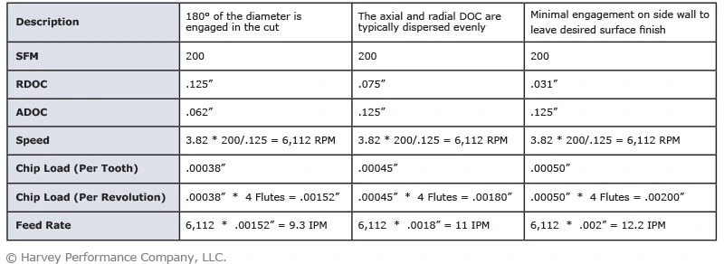
Machining feeds and speeds are critical parameters that determine tool performance, surface finish, dimensional accuracy, and tool life—especially in high-precision 3, 4, and 5-axis milling and turning operations requiring tight tolerances (±0.0005″ or better). Optimal values depend on workpiece material, tooling (material, geometry, coating), machine rigidity, coolant application, and depth of cut. The following table provides general starting parameters for common materials used in precision prototyping and low-volume production at Honyo Prototype.
| Material | Operation | Tool Type | Spindle Speed (RPM) | Feed Rate (IPM) | Chip Load (per tooth) | Depth of Cut (max, axial) | Notes |
|---|---|---|---|---|---|---|---|
| Aluminum 6061-T6 | 3–5 Axis Milling | Carbide end mill, 2–4 flute, TiAlN coated | 6,000 – 12,000 | 120 – 300 | 0.004 – 0.010 | ≤0.75″ | Use high feed rates; avoid dwelling. Flood coolant recommended for tight tolerance features. |
| Aluminum 6061-T6 | Turning | Carbide insert, sharp edge | 800 – 1,500 (SFM) | 0.010 – 0.020 (IPT) | 0.008 – 0.015 | 0.100″ – 0.200″ | Maintain constant surface speed (CSS). Use fine finishes for sealing surfaces. |
| 4140 Steel (annealed) | 3–5 Axis Milling | Carbide end mill, 4–6 flute, AlTiN coated | 1,200 – 2,500 | 40 – 100 | 0.002 – 0.004 | ≤0.50″ | Reduce speeds for hardened conditions (>40 HRC). Peck drilling with coolant for deep holes. |
| 4140 Steel (annealed) | Turning | Carbide insert, CVD coated | 300 – 600 (SFM) | 0.006 – 0.012 (IPT) | 0.005 – 0.010 | 0.100″ – 0.250″ | Use wiper inserts for fine finishes. Monitor for built-up edge. |
| ABS (thermoplastic) | 3–5 Axis Milling | Carbide, 2 flute, polished flute | 8,000 – 15,000 | 100 – 200 | 0.003 – 0.006 | ≤0.25″ | Avoid heat buildup. Use air blast or light mist. Sharp tools critical to prevent melting. |
| ABS | Turning | High-speed steel (HSS) or polished carbide | 1,000 – 2,000 (SFM) | 0.005 – 0.010 (IPT) | 0.004 – 0.008 | 0.050″ – 0.100″ | Light cuts; minimal tool pressure to avoid deformation. |
| Nylon 6/6 (unfilled) | 3–5 Axis Milling | 2-flute carbide, polished | 6,000 – 10,000 | 80 – 150 | 0.003 – 0.005 | ≤0.20″ | Use sharp tools and air cooling. Pre-drill deep holes. Slight oversizing likely due to thermal expansion. |
| Nylon 6/6 | Turning | Polished HSS or carbide | 500 – 900 (SFM) | 0.004 – 0.008 (IPT) | 0.003 – 0.007 | 0.050″ – 0.100″ | Allow for springback. Use steady rest for long parts. Avoid excessive clamping force. |
Notes on Tight Tolerance Machining:
For ±0.0005″ tolerances, thermal stability is critical. Allow machine and material to reach ambient temperature.
Use rigid tool holders (e.g., hydraulic or shrink fit) and minimize tool overhang.
Implement climb milling for better accuracy and surface finish in milling operations.
Perform in-process probing or laser measurement for critical dimensions, especially in 5-axis setups.
Material homogeneity and stress relief are essential—particularly in aluminum and steel for precision components.
These values are starting recommendations; final parameters should be fine-tuned based on specific tooling, machine capability, and inspection feedback.
From CAD to Part: The Process
Honyo Prototype integrates machining feeds and speeds optimization as a critical technical element within our established workflow, ensuring precision and efficiency without adding discrete steps. This parameterization occurs during Design for Manufacturability (DFM) analysis and is rigorously validated in Production. Below is the precise integration within our standard process:
Upload CAD
Clients submit validated 3D CAD models (STEP, IGES, native formats). Our system performs initial geometry validation but does not generate feeds/speeds at this stage. Material specification and critical tolerances provided by the client form the foundational input for subsequent machining parameterization.
AI Quote
Our AI-driven quoting engine analyzes geometry complexity, feature types, and client-specified material to estimate machine time and cost. While this phase considers approximate cycle times based on historical data, it does not calculate final feeds/speeds. The AI identifies potential high-risk features requiring deeper DFM analysis, such as thin walls or deep cavities, which directly impact optimal cutting parameters.
DFM (Design for Manufacturability)
This is the phase where feeds and speeds are technically defined. Our manufacturing engineers and CAM specialists perform detailed analysis:
Material properties (e.g., aluminum 6061-T6 vs. stainless steel 304) dictate base speeds and chip load calculations.
Feature geometry (pocket depths, wall thicknesses, radii) determines tool selection, stepovers, and stepdowns.
Machine capabilities (spindle power, rigidity, maximum RPM) constrain achievable parameters.
Surface finish and tolerance requirements drive finish pass strategies.
Using industry-standard CAM software (Mastercam, Fusion 360), we generate optimized toolpaths with precisely calculated feeds (IPM), speeds (SFM/RPM), and depths of cut. Critical parameters undergo peer review before approval. The DFM report explicitly documents key machining parameters for client transparency.
Production
Feeds and speeds are executed and validated here:
NC programs with finalized parameters are loaded onto CNC machines (mills, lathes).
First Article Inspection (FAI) includes verification of surface finish, dimensional accuracy, and absence of tool marks or chatter – direct indicators of correct feed/speed application.
In-process checks monitor tool wear; parameters may be dynamically adjusted within tolerance limits based on real-time machining feedback.
All critical parameters are recorded in the production log for traceability.
Delivery
Final inspection reports include confirmation that parts were manufactured per the approved DFM parameters. Production data (including any validated parameter adjustments) feeds back into our knowledge base to continuously refine future DFM calculations.
Feeds/Speeds Integration Summary
| Phase | Role in Feeds/Speeds Process | Key Activities | Output for Feeds/Speeds |
|---|---|---|---|
| DFM | Definition & Optimization | Material analysis, toolpath simulation, parameter calculation, peer review | Approved, documented feeds/speeds in NC code |
| Production | Execution, Validation & Adjustment | Program loading, FAI, in-process monitoring, tool wear management | Verified parameters, production log data |
This structured approach ensures feeds and speeds are not arbitrary settings but engineered parameters derived from material science, machine dynamics, and geometric requirements. Our closed-loop process guarantees that theoretical DFM calculations are proven effective during actual machining, directly contributing to on-time delivery of dimensionally accurate, high-integrity prototypes.
Start Your Project
Optimize your machining performance with expert guidance on feeds and speeds tailored to your specific materials and equipment. At Honyo Prototype, our precision CNC machining services are backed by years of in-house manufacturing experience at our Shenzhen factory.
For technical support or custom machining consultations, contact Susan Leo at [email protected] to ensure your operations run efficiently and with maximum precision.
🚀 Rapid Prototyping Estimator
Estimate rough cost index based on volume.