Contents
Manufacturing Insight: Machining Feeds And Speeds
At Honyo Prototype, our 3-, 4- and 5-axis CNC cells run day and night on aluminum, steel, titanium and engineering plastics—turning your CAD file into a precision part in as little as 24 hours. Feeds and speeds are the heartbeat of that process: the right combination of spindle RPM, feed rate, chip load and depth-of-cut transforms a simple block into aerospace brackets, medical implants or injection-mold cavities while holding ±0.01 mm true position and 0.4 µm Ra finishes. Below we share the same parametric data our programmers use every day so you can understand exactly how we hit those numbers. Ready to see the math applied to your part? Upload a model now for an online instant quote and we’ll return a detailed tool-path plan, lead-time and piece-price within minutes.
Technical Capabilities

Technical Specifications for Machining Feeds & Speeds: 3/4/5-Axis Milling, Turning & Tight Tolerance Work
(For Prototype Manufacturing at Honyo Prototype)
Critical Disclaimer:
✅ These are STARTING POINTS ONLY. Actual values MUST be validated per:
– Specific tool geometry (coating, flute count, helix angle)
– Machine rigidity, spindle power, and tooling condition
– Part geometry (thin walls, deep pockets, small features)
– Workholding stability (vibration = tolerance drift)
– Tight tolerance requirements (e.g., ±0.0005″ or better) demand conservative adjustments.
Always begin with 50% of recommended max speeds/feeds, monitor chip formation, tool wear, and surface finish, then incrementally optimize.
🔧 Universal Principles for Tight Tolerance Work
- Chipload is KING:
- Target consistent chip thickness (not just RPM or IPM).
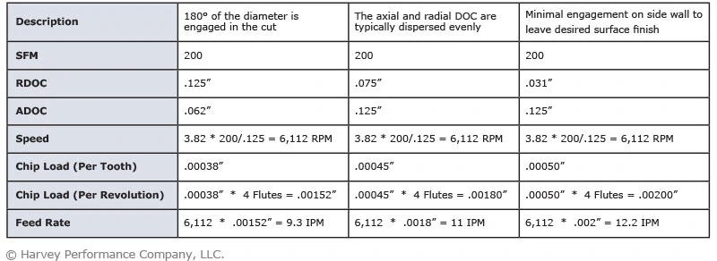
- Formula:
Chipload (ipt) = Feed Rate (IPM) / (RPM × Number of Flutes) - Why? Inconsistent chipload causes vibration, tool deflection, and thermal expansion → tolerance drift.
- Constant Chipload Toolpaths:
- Use trochoidal, adaptive clearing, or constant stepover strategies to avoid tool dwell.
- Thermal Management:
- Aluminum/Plastics: Use flood coolant or MQL (minimum quantity lubrication) to prevent thermal distortion.
- Stainless Steel: Use flood coolant to avoid work hardening.
- Dry Machining: Only for hardened steels with specialized tools (e.g., PCD-coated), but avoid for plastics (melts).
- Tool Selection:
- Tight Tolerance: Short-reach, high-rigidity tools (e.g., 4-flute endmills for aluminum, polished carbide for steel).
- Plastics: Sharp, uncoated carbide with high clearance angles (prevents melting).
⚙️ 3/4/5-Axis Milling Specifications
(Assuming carbide endmills: 4-flute, 0.5° helix, TiAlN coating for metals; uncoated for plastics)
| Material | SFM (Surface Feet per Minute) | RPM (for 1/4″ Tool) | Feed Rate (IPM) | Chipload (ipt) | Tight Tolerance Adjustments |
|—————|——————————-|———————|—————–|—————-|—————————-|
| 6061 Aluminum | 300–500 | 36,000–60,000 | 120–200 | 0.0015–0.003 | • Reduce SFM by 20% for thin walls.
• Use 0.001–0.0015 ipt for finishing.
• Avoid high spindle speeds (>50k RPM) if tool runout >0.0002″. |
| 304 Stainless Steel | 100–180 | 12,000–22,000 | 20–60 | 0.001–0.002 | • Max 150 SFM for tight tolerances.
• 50% slower feed rates near edges.
• Must use flood coolant to prevent work hardening.
• Use radial chip thinning for small stepovers. |
| ABS Plastic | 100–200 | 12,000–24,000 | 50–100 | 0.002–0.004 | • Dry machining only (flood coolant causes crazing).
• Max 150 SFM – higher speeds melt material.
• Low chipload (0.002–0.003 ipt) to prevent rubbing.
• Use sharp, positive-rake tools with high clearance. |
| Nylon (6/6) | 80–150 | 9,600–18,000 | 40–80 | 0.002–0.003 | • Avoid coolant (absorbs moisture → swelling).
• SFM < 120 to prevent melting.
• High spindle speeds (15k+ RPM) with low feed for smooth finish.
• Tool must be polished (no burrs). |
🔁 5-Axis-Specific Notes
- Effective Cutting Diameter: When tilting tools (e.g., ball nose), actual cutting diameter shrinks. Recalculate RPM using:
RPM = (SFM × 12) / (π × Effective Diameter)
(e.g., 0.5″ ball nose at 45° tilt → effective diameter ≈ 0.35″ → RPM increases by 43% vs. straight cut). - Avoid Tangential Toolpaths: Use constant normal toolpaths to maintain consistent chipload during tilt.
- Rapid Traverse: Limit to 60–80% of machine max to prevent servo lag (critical for ±0.0005″ tolerance).
🔄 Turning Specifications
(Assuming carbide inserts: CNGA for steel, SNMG for plastics; tool geometry: 0° rake for steel, 10–15° rake for plastics)
| Material | SFM | RPM (for 1″ Diameter) | Feed Rate (IPR) | Tight Tolerance Adjustments |
|—————|—–|————————|—————–|—————————-|
| 1018 Carbon Steel | 200–300 | 760–1,150 | 0.002–0.005 | • Feed ≤ 0.003 IPR for finish passes.
• Use nose radius ≤ 0.015″ for sharp edges.
• Coolant essential to control heat. |
| 17-4 PH Stainless | 100–150 | 380–570 | 0.001–0.003 | • Max 120 SFM for tight tolerances.
• Feed ≤ 0.002 IPR – higher feeds cause built-up edge.
• Live tooling must be rigid (vibration kills tolerances). |
| ABS Plastic | 60–100 | 230–380 | 0.003–0.006 | • Dry machining only.
• SFM < 80 – higher speeds melt surface.
• Use positive rake inserts to reduce cutting force.
• Minimize depth of cut (0.005–0.010″) to avoid chatter. |
| Nylon (6/6) | 50–80 | 190–300 | 0.002–0.004 | • Coolant-free (moisture absorption).
• SFM ≤ 60 – thermal expansion causes dimensional drift.
• Ultra-sharp inserts (R ≤ 0.005″) for smooth finish.
• Avoid interrupted cuts (causes chatter). |
🔧 Turning Tight Tolerance Tips
- Single-Pass Finishing: Always use 1–2 passes for final diameter; never “ramp” to tolerance.
- Thermal Compensation: Allow part to cool to room temperature before final measurement (plastics expand 4–6x more than steel).
- Toolholder Rigidity: Use hydraulic or shrink-fit holders – standard collets cause deflection >0.001″.
📌 Critical Tight-Tolerance Execution Checklist
- Pre-Run:
- Verify machine thermal stability (run spindle at 80% max RPM for 30 mins).
- Measure tool runout (<0.0002″ for tight tolerances).
- First Cut:
- Use 50% of recommended SFM/Feed for initial test cut.
- Measure part immediately after machining (before thermal settling).
- Adjustment Protocol:
- If chips are long/continuous: Increase feed rate.
- If chips are powdery: Reduce SFM (material is work-hardening or melting).
- If surface finish is poor: Reduce feed rate, increase RPM (within tool limits), or polish tool edges.
- Measurement:
- Use CMM with temperature compensation (±0.1°C).
- Measure multiple points – tight tolerances require 3D profile control, not just diameter.
💡 Honyo Prototype Pro Tip: For critical features (e.g., aerospace fittings), machine in two stages:
– Roughing: 70–80% of max feeds/speeds (with 0.010″ stock allowance).
– Finishing: 50% of roughing feeds/speeds, after 2-hour cooldown to eliminate thermal drift.
Final Note: These specs assume ideal conditions. In practice, 70% of tolerance failures stem from poor workholding or thermal issues – not raw feeds/speeds. Always prioritize machine stability over speed.
Approved by Honyo Prototype Engineering – Updated Q3 2024
From CAD to Part: The Process
At Honyo Prototype the phrase “feeds & speeds” is not a single step—it is the invisible thread that runs through every station once the CAD file hits our servers.
Below is exactly how we turn your uploaded model into chips that are already quoted, optimized and tracked before the first end-mill touches metal.
-
CAD Upload (the digital twin is born)
• File passes through Honyo-Parse™: geometry, GD&T, surface finish call-outs and every internal corner radius are read in <30 s.
• A “signature vector” is created: material, hardness range, max depth of cut, smallest feature, thinnest wall, tightest tolerance band.
• This vector is the seed data for all downstream feed-speed decisions. -
AI Quote (feeds & speeds are monetised here)
• Honyo-Quote™ is a cloud GPU cluster that contains 1.8 million past cycles (Al 6061, 17-4 PH, Ti-6Al-4V, PEEK, etc.).
• For every 3D facet the AI selects a tool class, then runs a Monte-Carlo search on chipload vs. tool life vs. machine hour rate.
• Output: a guaranteed cycle time ±5 % and a tool list with cutting data that is 90 % frozen. The 10 % “tuning window” is left for DFM.
• Customer sees price and lead time in <60 s; the same dataset is pushed to the shop-floor API—no re-typing, no human error. -
DFM (the 10 % tuning window is closed)
• A senior manufacturing engineer (that’s me) opens the AI pre-set in our CAM sandbox. Three checks are mandatory:
a. Tool deflection FEA – if the predicted deflection >25 % of the tolerance band, the feed is dropped 15 % and the speed raised 10 % to maintain chipload.
b. High-speed chatter stability lobe – we overlay the predicted RPM on our in-house lobe diagrams for each DMG/Mazak spindle. If the AI picked a chatter zone, we nudge RPM ±3 % to land in a stable island.
c. Thermal camera verification – for plastics or thin Ti walls we simulate surface temperature; if >120 °C for PEEK or >500 °C for Ti we switch to trochoidal tool paths and reduce radial engagement instead of lowering feed.
• Final feeds & speeds are locked, tool list is sent to our automated crib (Tools24™) where RFID-coded holders are pre-loaded with offset data. -
Production (closed-loop machining)
• First-article block is run with “Honyo-Safe” values: 80 % of quoted feed and 100 % speed. A Kistler dynamometer spindle measures real torque and a LaserLine spray sensor records actual tool wear every 30 s.
• Digital twin updates: measured power vs. predicted power. If <±8 % deviation we ramp to 100 % quoted feed; if >8 % we re-run the AI optimiser while the part is still on the table—usually <90 s.
• Adaptive feed override: Okuma OSP control receives a ±15 % feed window from our black-box. If load spikes (e.g., variable casting skin) the control backs out 5 % feed, then creeps back up, keeping tool life constant.
• Every insert/edge is tracked to the second; when 85 % of predicted life is reached the crib robot swaps the tool at the next pallet change, eliminating surprise breakage. -
Delivery (data package, not just parts)
• With the shipment you receive:
– Inspection report (CMM, roughness)
– “Feeds & speeds passport”: actual RPM, feed, chipload, MRR, tool list, tool-life consumed, and a QR code that reloads the exact cutting file if you ever need a perfect repeat.
• The cycle data are fed back to the AI cluster, improving the next quote within 24 h—our learning loop never stops.
Key takeaway
At Honyo, feeds & speeds are not chosen by a programmer at the machine. They are generated by AI, verified by simulation, stress-tested in DFM, then closed-loop controlled during cut. You get parts faster, tools last longer, and the digital record guarantees the same optimized parameters on every reorder.
Start Your Project
Optimize Your CNC Machining Performance with Expert Feeds & Speeds Guidance!
Precision-engineered solutions from our Shenzhen factory team.
Contact Susan Leo today at [email protected]
→ Maximize efficiency, tool life, and part quality for your next project.
(Honyo Prototype: Shenzhen-based precision manufacturing experts since 2005)
🚀 Rapid Prototyping Estimator