Contents
Manufacturing Insight: Machining Cutting Tools
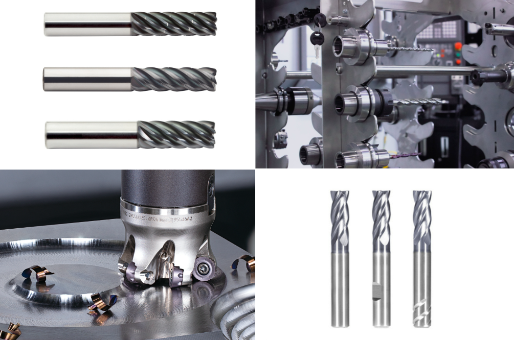
Precision Machining Starts with Optimal Cutting Tools
At Honyo Prototype, we recognize that cutting tool selection and performance are foundational to achieving micron-level tolerances, superior surface finishes, and efficient production cycles in CNC machining. Our engineering team leverages deep expertise in tool geometry, substrate materials, and coating technologies to optimize every machining operation—whether for complex aerospace components, medical device housings, or high-wear industrial parts. We meticulously match cutting tools to your specific material properties, feature geometries, and throughput requirements, ensuring minimal tool wear, reduced cycle times, and consistent part quality across aluminum, titanium, stainless steel, and engineered plastics.
Honyo’s integrated CNC machining services combine advanced multi-axis capabilities with rigorous process validation, transforming your designs into precision-engineered prototypes and low-volume production runs. Our commitment to cutting-edge tooling strategies directly translates to cost-effective solutions without compromising on accuracy or repeatability. To accelerate your project timeline, utilize our Online Instant Quote platform—submit CAD files and specifications for rapid, transparent pricing and manufacturability feedback within hours, not days. Partner with Honyo to turn machining challenges into competitive advantages.
Technical Capabilities
Technical specifications for machining cutting tools used in 3/4/5-axis milling, turning, and tight-tolerance applications are critical to achieving precision, surface finish, and dimensional accuracy. These tools must be optimized for the workpiece material and the complexity of the machining process. Below is a summary of key technical attributes for cutting tools across common materials: Aluminum, Steel, ABS, and Nylon.
| Feature | 3/4/5-Axis Milling Tools | Turning Tools | Material-Specific Considerations |
|---|---|---|---|
| Tool Material | Solid carbide, carbide with TiAlN or AlTiN coating, polycrystalline diamond (PCD) for non-ferrous | Carbide inserts (CVD/PVD coated), cermet, ceramic for high-speed steel turning | Aluminum: Use sharp PCD or uncoated carbide to prevent built-up edge. Steel: AlTiN-coated carbide or ceramic inserts for heat resistance. ABS/Nylon: High-speed steel or uncoated carbide with high rake angles to reduce melting. |
| Flute Count | 2–6 flutes: 2–3 for aluminum (chip clearance), 4–6 for steel (finish and rigidity) | Single-point geometry; no flutes | Aluminum: Low flute count for chip evacuation. Steel: Higher flute count for surface finish. Plastics: 2-flute end mills to avoid heat buildup. |
| Helix Angle | 30°–45°: 35°–40° for steel (strength), 40°–45° for aluminum (chip flow) | N/A (insert rake angle used instead) | Aluminum: High helix (40°–45°) for smooth shearing. Steel: Moderate helix (30°–35°) for edge strength. Plastics: High helix to reduce melting. |
| Tolerance Capability | ±0.005 mm (±0.0002″) achievable with high-precision toolholders and thermal compensation | ±0.01 mm (±0.0004″) typical; tighter with CNC control and tool presetting | Tight-tolerance work requires tool runout < 0.003 mm, rigid setups, and in-process probing. Steel and aluminum allow tighter tolerances than plastics due to dimensional stability. |
| Cutting Speed (Vc) | Aluminum: 300–1000 m/min; Steel: 80–200 m/min; ABS/Nylon: 150–300 m/min | Aluminum: 400–1000 m/min; Steel: 100–250 m/min; Plastics: 200–400 m/min | High speeds for aluminum and plastics require secure workholding. Steel requires lower speeds with high torque. |
| Feed Rate (fz) | 0.05–0.2 mm/tooth (adjust based on depth of cut and finish requirements) | 0.05–0.3 mm/rev depending on insert nose radius and finish | Plastics require moderate feed to avoid melting; steel requires consistent feed to maintain tool life. |
| Tool Holding | High-precision shrink fit or hydraulic chucks with runout < 0.003 mm | Precision boring bars and collet systems | Essential for tight-tolerance and multi-axis work to minimize vibration and deflection. |
| Coolant Delivery | Through-spindle coolant (high pressure for deep cavities in steel) | External flood or through-tool coolant | Aluminum: Minimal or air blast to avoid staining. Steel: High-pressure coolant for chip control. Plastics: Air or minimal coolant to prevent warping. |
These specifications support high-accuracy machining across complex geometries in 3/4/5-axis platforms and turning centers, ensuring repeatability and surface quality within tight tolerances. Material behavior under heat and chip formation directly influences tool selection and process parameters.
From CAD to Part: The Process

Honyo Prototype Machining Cutting Tools Process Overview
Our end-to-end workflow for manufacturing precision cutting tools—including end mills, drills, inserts, and custom geometries—ensures rapid turnaround without compromising on quality or technical rigor. The process is engineered to minimize client risk and accelerate time-to-market through integrated digital and physical validation steps.
CAD Upload and Data Intake
Clients initiate the process via our secure, ISO 27001-certified portal, uploading native CAD files (STEP, IGES, Parasolid) or industry-standard 2D/3D drawings. The system automatically validates file integrity, checks for geometric completeness, and flags missing critical features such as flute profiles, helix angles, or relief surfaces. All data undergoes immediate encryption, with version control and access restricted to authorized engineering personnel only.
AI-Powered Quoting with Engineering Oversight
Uploaded designs enter our proprietary AI quoting engine, which analyzes over 200 geometric and material parameters—including substrate type (e.g., carbide grade K30, HSS-Co), coating requirements (TiAlN, AlCrN), and tolerance bands (±0.005mm typical). The AI generates a preliminary quote within 90 minutes, covering material costs, machine hours, and finishing steps. Crucially, a Senior Manufacturing Engineer reviews all AI outputs to verify feasibility, adjust for shop-floor realities like toolholder compatibility, and identify potential cost-saving alternatives (e.g., recommending a modified clearance angle to extend tool life). Clients receive a transparent quote with technical annotations explaining cost drivers.
DFM Analysis and Collaborative Refinement
Our DFM phase is iterative and client-engaged. Engineers perform granular manufacturability checks using CAM simulation tools, focusing on:
Toolpath collision risks in complex gash geometries
Feasibility of micro-features (e.g., chipbreakers <0.1mm radius)
Stress concentration points in asymmetric designs
Coating adhesion challenges on sharp edges
A formal DFM report details actionable recommendations—such as adjusting land widths for grinding stability or modifying flute spacing to prevent chatter—with tolerance impact assessments. Clients approve revisions via our portal before proceeding, ensuring alignment on performance trade-offs.
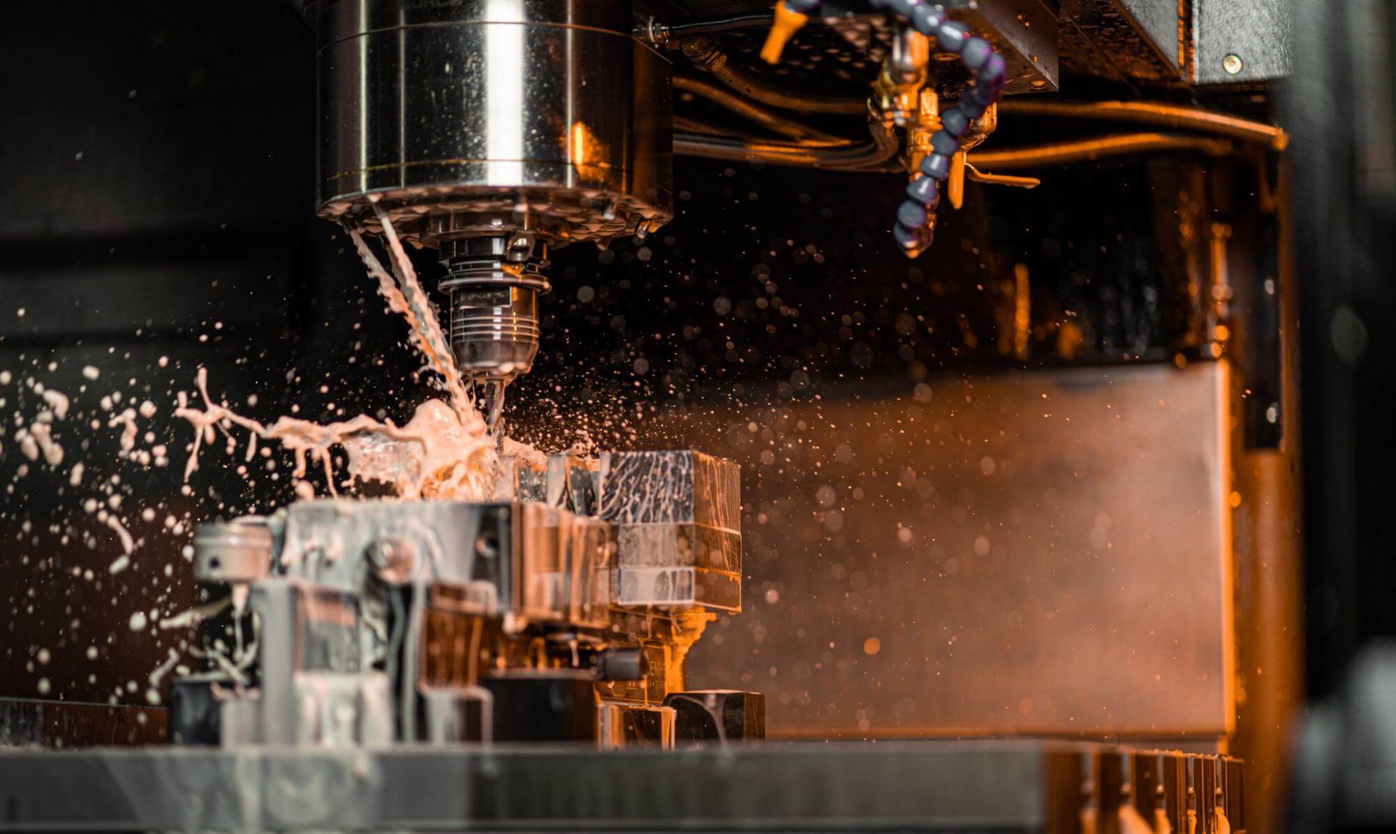
Precision Production and In-Process Validation
Approved designs move to dedicated CNC grinding cells (typically Studer S41 or ANCA MX7 machines) with environmental controls maintaining ±0.5°C stability. Key production stages include:
Sub-micron grinding of flutes and cutting edges using diamond/CBN wheels
Laser marking of serial numbers and geometry codes
In-machine probing for critical dimensions (core diameter, OAL, corner radius)
100% post-process CMM inspection against ASME B94.19 standards
All measurement data is stored digitally, with real-time SPC monitoring for process drift. For coated tools, we validate thickness uniformity via XRF spectroscopy and adhesion through Rockwell indentation tests.
Delivery and Technical Handoff
Finished tools undergo rigorous packaging: vacuum-sealed with desiccant for coated tools, or rigid foam inserts for uncoated geometries, shipped via tracked courier with shock-monitoring labels. Each delivery includes:
Signed inspection certificate with actual vs. nominal dimensions
Coating test reports (if applicable)
Recommended operating parameters (RPM, feed rates, coolant types)
Lifetime performance tracking access via our client portal
Typical lead times vary by complexity as shown below:
| Tool Complexity Tier | Example Features | Standard Lead Time | Max Tolerance Capability |
|---|---|---|---|
| Tier 1: Standard | 2-flute end mills, standard drills | 5-7 business days | ±0.010 mm |
| Tier 2: High Precision | Variable helix, tapered geometries | 10-12 business days | ±0.005 mm |
| Tier 3: Advanced | Micro-tools (<1mm), asymmetric profiles | 15-18 business days | ±0.002 mm |
This structured workflow—combining AI efficiency with deep manufacturing expertise—ensures cutting tools meet stringent performance demands while reducing client time-to-production by up to 40% versus traditional suppliers. We maintain full traceability from CAD to crate, providing engineering-grade documentation at every phase.
Start Your Project
Looking for high-performance machining cutting tools engineered for precision and durability? Contact Susan Leo today at [email protected] to discuss your project requirements. Backed by our state-of-the-art manufacturing facility in Shenzhen, we deliver reliable, high-quality cutting solutions tailored to your production needs. Let Honyo Prototype be your trusted partner in precision machining.
🚀 Rapid Prototyping Estimator
Estimate rough cost index based on volume.