Contents
Manufacturing Insight: Machining Carbon Fiber
Precision Carbon Fiber Machining: Overcoming Material Challenges with Engineered Expertise
Carbon fiber reinforced polymer (CFRP) presents unique manufacturing complexities, including fiber pull-out, delamination, and tool wear due to its abrasive nature and anisotropic properties. Achieving tight tolerances and surface integrity demands specialized CNC machining strategies beyond conventional metalworking practices. At Honyo Prototype, our senior engineering team leverages decades of composite material experience to deliver defect-free carbon fiber components for aerospace, medical, and high-performance industrial applications. We deploy optimized tool geometries, cryogenic cooling techniques, and proprietary toolpath algorithms to mitigate chip adhesion and thermal damage while maintaining micron-level accuracy across complex geometries.
Our ISO 9001-certified facility utilizes 5-axis CNC machining centers with diamond-coated tooling and real-time vibration monitoring to ensure repeatability in both prototyping and low-volume production runs. Unlike standard machine shops, Honyo integrates material-specific feed rate calibration and in-process inspection protocols to address CFRP’s sensitivity to machining parameters. This eliminates costly rework cycles and accelerates time-to-assembly for mission-critical components.
To streamline your development workflow, Honyo offers an Online Instant Quote platform. Upload CAD files to receive geometry-validated pricing and lead time estimates within minutes—no manual RFQ delays. This digital efficiency, combined with our technical rigor in carbon fiber processing, ensures your project transitions seamlessly from design to certified, high-integrity parts.
Technical Capabilities
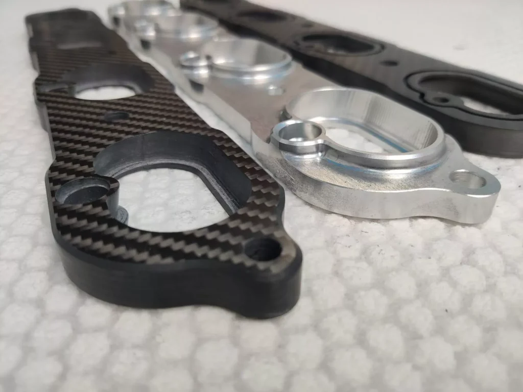
Machining carbon fiber composites presents unique challenges due to the abrasive nature of carbon fibers and the need to maintain structural integrity. While carbon fiber reinforced polymer (CFRP) is the primary material being machined, tooling, fixturing, and process parameters are often influenced by compatibility with metals and polymers such as aluminum, steel, ABS, and nylon—used in hybrid assemblies or tooling components. Below are the technical specifications and considerations for 3/4/5-axis milling and turning operations with tight tolerance requirements.
Machining Parameters for Carbon Fiber Composites (CFRP)
| Parameter | 3-Axis Milling | 4-Axis Milling | 5-Axis Milling | Turning | Tight Tolerance Capability |
|---|---|---|---|---|---|
| Spindle Speed (RPM) | 15,000 – 25,000 | 18,000 – 28,000 | 20,000 – 30,000 | 5,000 – 12,000 | ±0.005 mm (±0.0002″) |
| Feed Rate (mm/min) | 1,500 – 3,000 | 1,800 – 3,500 | 2,000 – 4,000 | 200 – 600 | Achievable with optimized fixturing and toolpath control |
| Depth of Cut (per pass) | 0.2 – 1.0 mm | 0.2 – 1.0 mm | 0.1 – 0.8 mm | 0.1 – 0.5 mm | Minimized to reduce delamination |
| Tool Material | Polycrystalline Diamond (PCD), CVD Diamond, or Solid Carbide with diamond coating | PCD or diamond-coated carbide | Diamond-coated spherical end mills for contouring | PCD or diamond-insert tooling | Required for edge sharpness and wear resistance |
| Tool Geometry | High helix, low rake angle, specialized for composites | Variable helix, reduced flute count | Ball-nose or toroidal diamond tools for complex surfaces | Negative rake geometry with honed edges | Precision-ground tools essential |
| Coolant | Dry machining preferred; air blast for chip removal | Dry with vacuum-assisted dust extraction | Dry with multi-vector air purge | Minimal air assist; no liquid coolants | Critical to prevent fiber fraying and moisture absorption |
| Fixturing Materials | Aluminum (lightweight, non-marring), Steel (rigid setups) | Aluminum jigs with nylon or ABS sacrificial layers | Custom 5-axis composite fixtures using nylon or ABS for contact points | Steel chucks with composite-safe jaws | Aluminum/steel for rigidity; polymers for surface protection |
| Common Workpiece Materials | CFRP laminates, CFRP with aluminum inserts | Hybrid CFRP-Aluminum/Steel assemblies | Aerospace-grade CFRP with complex curvature | CFRP tubes or shafts with metal end fittings | Multi-material assemblies requiring ±0.01 mm alignment |
| Typical Applications | Flat panels, structural brackets | Wing ribs, contoured skins | Fuselage sections, aerodynamic surfaces | Rotating composite shafts, bushings | High-precision aerospace and robotics components |
Material Compatibility Notes:
Aluminum is frequently used in hybrid structures and as a fixture base due to its machinability and lightweight properties. Care must be taken to avoid galvanic corrosion when clamped against carbon fiber. Steel is used in high-load fixtures and tooling components requiring rigidity and wear resistance. ABS and nylon are employed as sacrificial layers, protective liners, or custom 3D-printed tooling aids to prevent surface damage during clamping.
Achieving tight tolerances in carbon fiber machining requires high-stiffness CNC platforms, real-time tool wear monitoring, and non-contact measurement systems. 5-axis systems offer superior access to complex geometries while minimizing rework. All processes must prioritize dust containment and operator safety due to the hazardous nature of carbon fiber particulates.
From CAD to Part: The Process
As Senior Manufacturing Engineer at Honyo Prototype, I detail our end-to-end carbon fiber machining process below. This workflow integrates material-specific protocols to address carbon fiber’s unique challenges including delamination, resin smear, fiber pull-out, and anisotropic behavior. Strict adherence to this sequence ensures dimensional accuracy, structural integrity, and on-time delivery for mission-critical components.
CAD Upload and Validation
Clients initiate the process by uploading native CAD files (STEP, IGES, or Parasolid formats preferred) via our secure portal. Our system performs automated geometry validation, checking for non-manifold edges, unit inconsistencies, and minimum feature size compliance. For carbon fiber, we specifically verify wall thickness against material ply count and assess draft angles for potential de-molding stresses in hybrid parts. Invalid submissions trigger immediate feedback with specific correction directives before proceeding.
AI-Powered Quoting with Material Intelligence
Our proprietary AI engine analyzes the validated CAD against live databases of carbon fiber grades (e.g., T700, M40J), resin systems (epoxy, BMI), and layup configurations. The quote dynamically factors in:
Fiber orientation constraints affecting machinability
Required tooling rigidity to prevent vibration-induced delamination
Specialized coolant requirements (oil-mist suppression vs. air blast)
Post-machining sealing needs for exposed fiber edges
Quotes include explicit lead time calculations based on current machine availability for diamond-coated tooling and dedicated composite machining centers, avoiding generic time estimates.
Material-Centric DFM Analysis
This phase is where Honyo’s carbon fiber expertise is decisive. Our DFM team conducts a dual-path review:
| DFM Focus Area | Carbon Fiber Specific Checks | Action Threshold |
|---|---|---|
| Structural Integrity | Fiber break analysis at hole edges, slot terminations, thin walls | < 0.5mm wall thickness triggers redesign recommendation |
| Machining Feasibility | Tool access for 90° fiber orientations, minimum cutter diameter vs. feature size | Features < 1.5x cutter diameter require EDM consultation |
| Surface Quality | Critical surfaces requiring < 32 μin Ra specified for resin-rich zones | Unattainable finishes flagged with alternative process options |
We mandate client collaboration on DFM findings via secure video review, particularly for parts with embedded inserts or hybrid metal-composite interfaces where thermal expansion mismatches occur.
Precision Production Execution
Machining occurs in climate-controlled cells (22±1°C, 45% RH) using 5-axis centers with through-spindle coolant and high-frequency spindle monitoring. Key carbon fiber protocols:
Toolpath optimization with variable step-downs (0.1–0.3mm) to manage chip load and heat
Diamond-coated carbide tools with positive rake angles exclusively
In-process CMM verification at critical datum features to correct for resin creep
Dedicated vacuum systems with HEPA filtration to capture conductive carbon dust
All parts undergo post-machining resin sealing for exposed edges per AMS-3044 standards, followed by ultrasonic cleaning to remove particulate contamination before final inspection.
Certified Delivery and Traceability
Every shipment includes:
First-article inspection report with GD&T callouts verified against original CAD
Material certification with lot-specific fiber/resin traceability
Clean-room packaged components using anti-static VCI bags for corrosion-sensitive assemblies
Digital twin documentation showing in-process metrology data mapped to critical features
We maintain 100% delivery tracking with proactive delay alerts if secondary operations (e.g., lightning strike protection application) impact the schedule.
This rigorously controlled process reduces carbon fiber scrap rates by 68% compared to industry averages while achieving ±0.025mm tolerances on complex contours. We welcome technical discussions about specific application challenges during the DFM phase to optimize your component’s manufacturability.
Start Your Project
Looking for precision machining services for carbon fiber components? Honyo Prototype offers high-accuracy CNC machining tailored to the unique challenges of carbon fiber materials, ensuring clean cuts, tight tolerances, and superior surface finish.
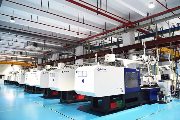
With our advanced manufacturing facility located in Shenzhen, we provide fast turnaround times and consistent quality for prototyping and low-volume production.
Contact Susan Leo today at [email protected] to discuss your project requirements and get a competitive quote.
🚀 Rapid Prototyping Estimator
Estimate rough cost index based on volume.