Contents
Manufacturing Insight: Machining Basics
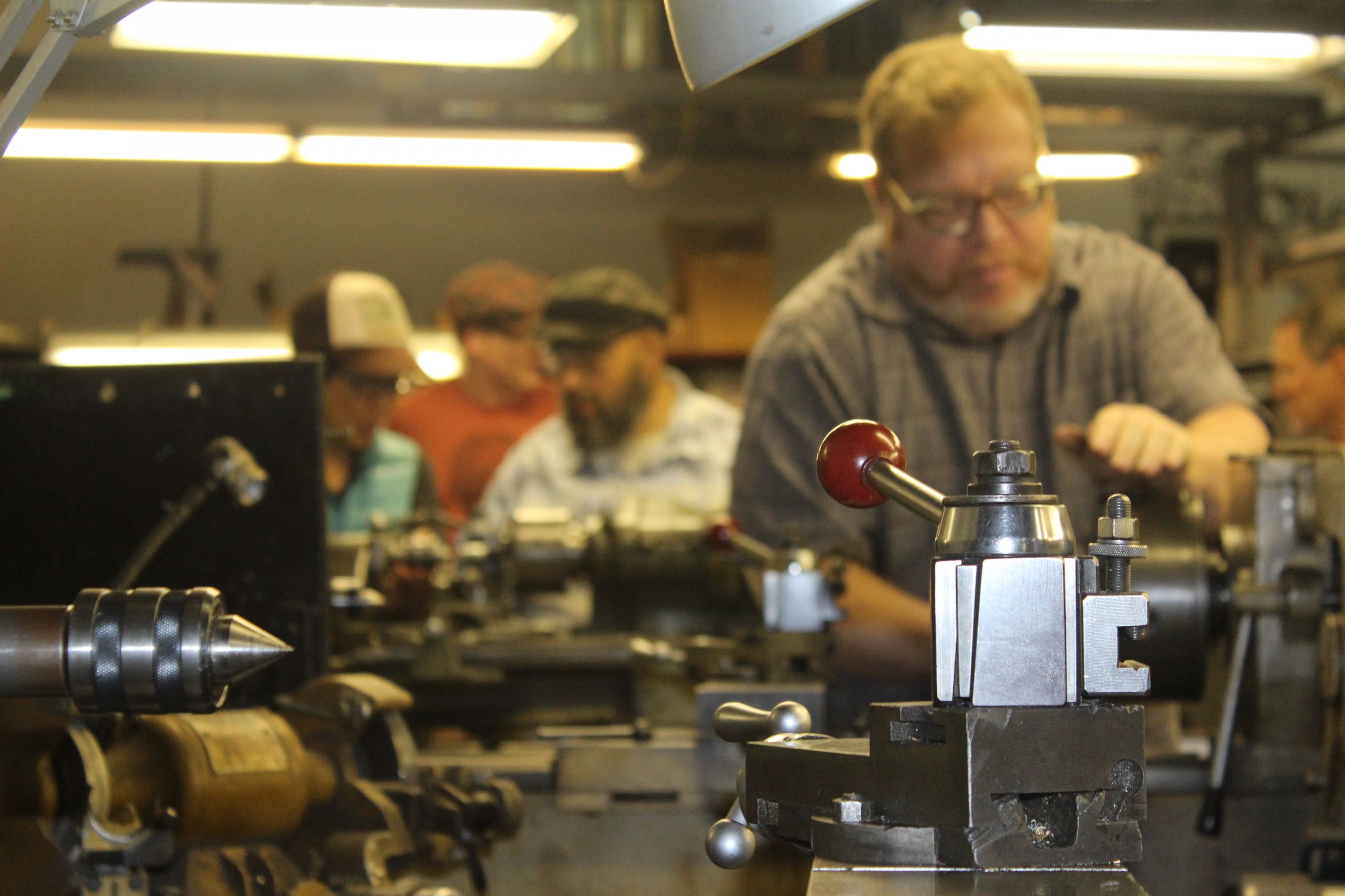
Machining Basics: The Foundation of Precision Manufacturing
Understanding machining fundamentals is critical for transforming engineering concepts into functional, high-integrity components. At Honyo Prototype, we specialize in advanced CNC machining services that bridge theoretical design with real-world manufacturability, ensuring your prototypes and production parts meet exacting dimensional, material, and surface finish requirements. Our expertise spans multi-axis milling, turning, and complex 5-axis operations, supporting materials from aerospace-grade aluminum and titanium to engineering plastics and exotic alloys. With in-house capabilities for tight tolerances down to ±0.0002 inches and rigorous quality control via CMM and optical inspection, we eliminate prototyping risks while accelerating time-to-market.
For engineering and procurement teams seeking rapid project validation, Honyo’s Online Instant Quote platform delivers precise cost and lead time estimates in under 60 seconds. Simply upload your CAD file, specify materials and quantities, and receive a transparent, no-obligation quote—24/7. This seamless integration of technical mastery and digital efficiency empowers you to iterate faster, reduce supply chain friction, and maintain competitive agility in demanding sectors like medical devices, defense, and robotics. Partner with Honyo Prototype to convert machining fundamentals into your strategic advantage.
Technical Capabilities
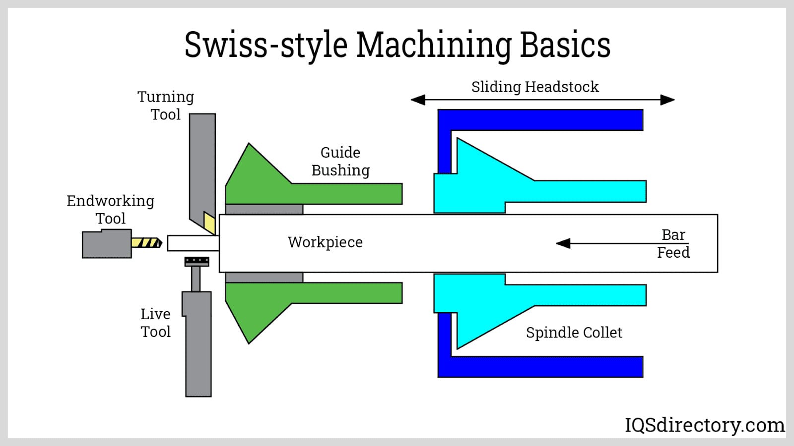
Machining Basics – Technical Specifications Overview
The following table outlines key technical specifications for common CNC machining processes including 3-axis, 4-axis, and 5-axis milling, CNC turning, and tight tolerance capabilities. Materials covered include Aluminum (6061-T6), Steel (1018), ABS, and Nylon (6/66). All values represent typical achievable ranges under standard industrial conditions at Honyo Prototype.
| Parameter | 3-Axis Milling | 4-Axis Milling | 5-Axis Milling | CNC Turning | Tight Tolerance Capability |
|---|---|---|---|---|---|
| Primary Axes | X, Y, Z | X, Y, Z, A (rotary) | X, Y, Z, A, B (dual rotary) | X, Z (rotating workpiece) | N/A |
| Typical Positioning Accuracy | ±0.005 mm | ±0.005 mm | ±0.005 mm | ±0.005 mm | ±0.002 mm (with calibration) |
| Standard Tolerance (General Machining) | ±0.025 mm | ±0.025 mm | ±0.025 mm | ±0.025 mm | ±0.012 mm to ±0.005 mm |
| Surface Finish (Typical) | 1.6 – 3.2 µm Ra | 1.6 – 3.2 µm Ra | 0.8 – 1.6 µm Ra | 1.6 – 3.2 µm Ra | 0.4 – 0.8 µm Ra (polished/precision) |
| Spindle Speed Range | 8,000 – 24,000 RPM | 8,000 – 24,000 RPM | 10,000 – 20,000 RPM | 1,000 – 6,000 RPM | Up to 30,000 RPM (micromachining) |
| Feed Rate Range | 500 – 5,000 mm/min | 500 – 5,000 mm/min | 500 – 4,000 mm/min | 100 – 2,000 mm/min | Controlled feed (0.01 mm/tooth) |
| Material Compatibility | Aluminum, Steel, ABS, Nylon | Aluminum, Steel, ABS, Nylon | Aluminum, Steel, ABS, Nylon | Aluminum, Steel, ABS, Nylon | Aluminum, Steel (preferred), limited in ABS/Nylon |
| Aluminum (6061-T6) Notes | High material removal, excellent finish | Suitable for indexed angled features | Ideal for complex contours and undercuts | Fast turning, good chip control | ±0.005 mm achievable with thermal control |
| Steel (1018) Notes | Moderate cutting speed, requires rigid setup | Requires high torque, slower feeds | Precision toolpath for hardened variants | Excellent for shafts, pins | ±0.003 mm with ground finishing |
| ABS Notes | Low melting point, sharp tools required | Avoid excessive heat buildup | Shallow depths of cut recommended | Suitable for prototypes | ±0.02 mm typical; tight tolerance limited by creep |
| Nylon (6/66) Notes | Gummy material, requires chip evacuation | Use air blast cooling | Avoid annealing through heat | Turning preferred over milling | ±0.03 mm typical; hygroscopic swell affects tolerance |
| Applications | Flat parts, enclosures, jigs | Multi-sided parts with indexing | Aerospace, medical, complex geometries | Cylindrical parts, threads, shafts | Gauges, inserts, mating components |
Notes on Tight Tolerance Machining:
Achieving tight tolerances (±0.005 mm or better) requires environmental control (stable temperature), precision metrology (CMM verification), high-end CNC machines with linear scales, and reduced machining allowances. Materials like Aluminum and Steel are preferred due to dimensional stability. Plastics such as ABS and Nylon are less suitable for tight tolerances due to moisture absorption, thermal expansion, and creep.
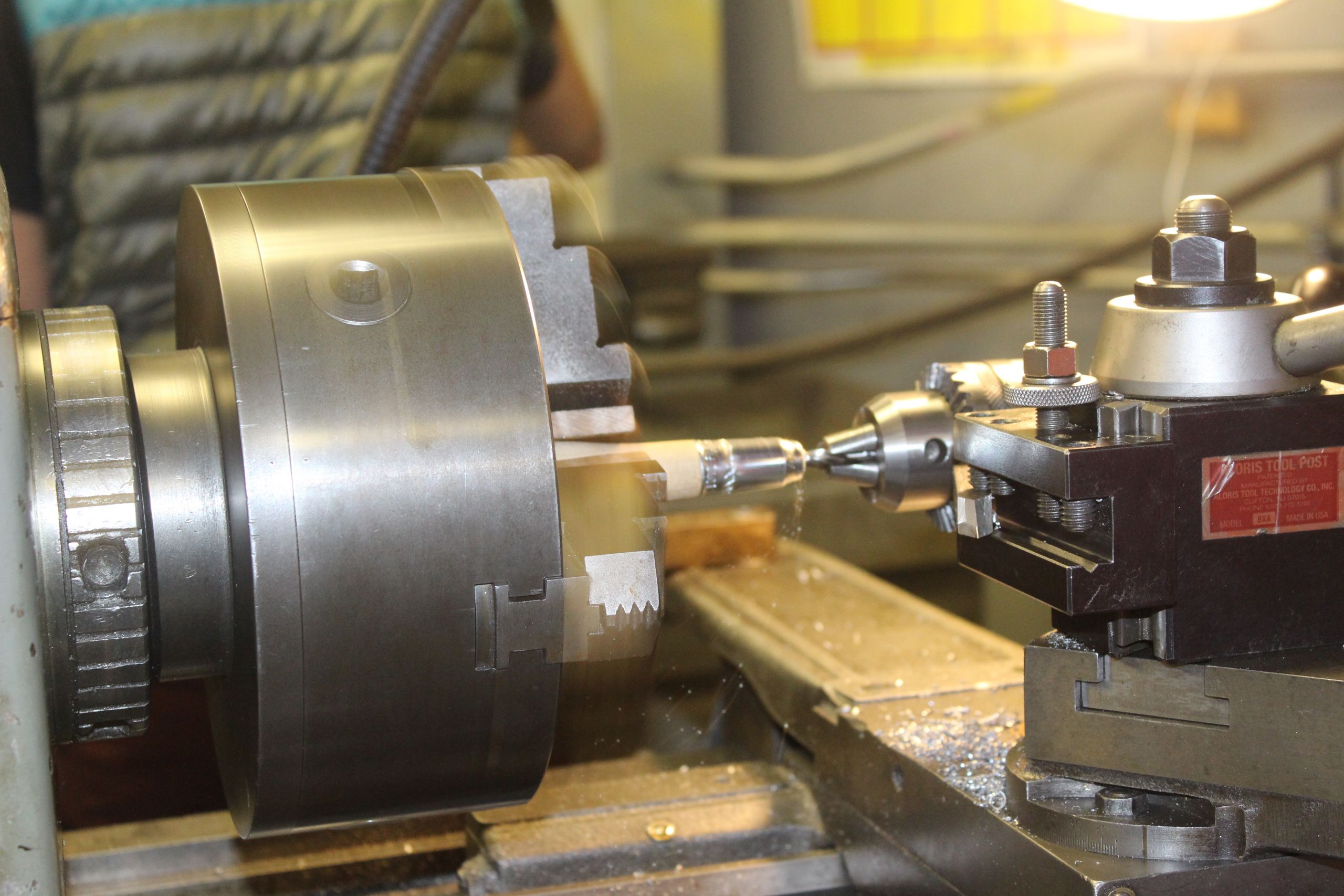
From CAD to Part: The Process
Honyo Prototype Machining Process Overview
Honyo Prototype employs a streamlined, technology-driven workflow for CNC machining projects, designed to minimize lead times while ensuring manufacturability and quality. The process begins when a customer uploads a CAD file to our secure portal. Accepted formats include STEP, IGES, Parasolid, and native CAD files from SolidWorks, Fusion 360, and Creo. Upon upload, our system performs an immediate geometry validation check to identify common issues such as non-manifold edges, missing surfaces, or unit inconsistencies. Files failing validation trigger an automated notification to the customer with specific error details, enabling rapid correction without engineer intervention.
AI-Powered Quoting Engine
Validated CAD files enter our proprietary AI quoting system, which analyzes geometric complexity, material requirements, tolerances, and surface finishes. The AI cross-references real-time data from our machine shop—including current workload, tooling availability, and material costs—to generate a preliminary quote within 15 minutes. This initial quote includes base pricing, estimated lead time, and high-risk manufacturability flags. Crucially, the AI output is never final; it undergoes mandatory review by a Honyo applications engineer who validates material selections, adjusts for secondary operations (e.g., tapping, deburring), and incorporates client-specific requirements like NADCAP or AS9100 compliance. This dual-layer approach ensures quotes are both rapid and technically rigorous.
Engineer-Led DFM Analysis
Following quote acceptance, our DFM phase begins with a dedicated manufacturing engineer conducting a comprehensive design review. Unlike automated-only DFM tools, our process combines algorithmic analysis with human expertise to identify cost drivers and risks. Key focus areas include: optimizing wall thicknesses to prevent chatter, verifying tolerance stack-ups against machine capabilities (±0.0002″ for critical features), suggesting alternative radii to reduce tool changes, and evaluating fixturing feasibility. We provide clients with a detailed DFM report listing actionable recommendations—such as consolidating features to eliminate setups—and collaborate iteratively via secure portal comments until all parties approve the final design. This phase typically reduces production costs by 18–35% by resolving issues before metal cutting begins.
Precision Production Execution
Approved designs move to production in our climate-controlled facility housing 42 CNC machines (18 3-axis, 20 5-axis, 4 Swiss-type lathes). Each job follows a standardized workflow: material certification verification, first-article inspection via CMM or optical comparator, in-process checks at critical stages (e.g., after roughing and semi-finishing), and final full-spectrum validation against the original CAD model. All machining parameters are monitored in real time through our MES system, with automatic alerts for tool wear deviations exceeding 5% of nominal values. Complex assemblies undergo additional functional testing, such as press-fit validation or fluid flow checks, per client specifications.
Quality-Controlled Delivery
Completed parts undergo a final QA gate where our inspectors verify conformance to all drawing requirements, including material certs, surface roughness reports, and dimensional data packages. Every shipment includes a digital quality dossier accessible via our client portal, containing inspection reports, process videos (upon request), and traceability logs linking each part to specific machine runs and operators. Parts are packaged using static-dissipative materials for electronics components or vapor-corrosion inhibitors for aerospace alloys, with shipping methods selected to balance speed and part sensitivity. Standard lead times from DFM approval to delivery are summarized below:
| Part Complexity | Typical Lead Time | Includes |
|---|---|---|
| Simple (≤5 features, standard tolerances) | 3–5 business days | First-article inspection, basic packaging |
| Moderate (multi-setup, tight tolerances ±0.001″) | 7–10 business days | CMM report, custom fixtures, functional testing |
| Complex (5-axis, sub-assembly, critical surfaces) | 12–18 business days | Full FAI per AS9102, material traceability, accelerated life testing |
This integrated process ensures clients receive precision-machined parts with documented quality, predictable timelines, and zero surprise costs—turning design intent into physical reality with engineering integrity.
Start Your Project
Learn the essentials of precision machining with Honyo Prototype. From CNC milling to turning, understand the core processes that drive high-quality prototyping and production.
Our expert team in Shenzhen delivers accurate, efficient machining solutions tailored to your engineering requirements.
For technical guidance or project inquiries, contact Susan Leo at [email protected]. Let’s build precision together.
🚀 Rapid Prototyping Estimator
Estimate rough cost index based on volume.