Contents
Manufacturing Insight: Machining Aluminum Wheels
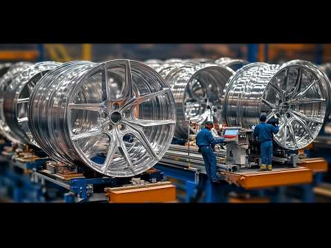
Precision Aluminum Wheel Machining for Demanding Applications
Honyo Prototype delivers advanced CNC machining solutions specifically engineered for high-performance aluminum wheels, serving automotive OEMs, motorsport teams, and Tier-1 suppliers. Our specialized process leverages 5-axis milling centers and optimized toolpaths to achieve micron-level tolerances on complex geometries, including intricate spoke designs, lightweight pockets, and critical bearing surfaces. We machine aerospace-grade alloys such as 6061-T6 and 7075-T6 with rigorously controlled parameters to eliminate chatter, minimize residual stress, and ensure structural integrity under extreme rotational loads.
Our technical expertise extends beyond machining to integrated post-processing, including precision balancing, anodizing coordination, and comprehensive CMM validation per ISO 17025 standards. This end-to-end control guarantees wheels meet stringent dynamic balance (G2.5 or better) and fatigue resistance requirements for applications ranging from EV performance rims to off-road racing components. Every project benefits from our proprietary fixturing systems that prevent distortion during high-MRR operations, directly addressing the thermal expansion challenges inherent in thin-walled aluminum structures.
Accelerate your development cycle with Honyo’s Online Instant Quote platform. Upload your STEP or IGES file to receive a detailed manufacturability analysis and competitive pricing within 2 hours—no sales interaction required. This transparent, data-driven quoting system reflects our commitment to reducing time-to-prototype while maintaining the exacting quality standards demanded by the automotive sector.
Honyo Prototype: Where Precision Machining Meets Rapid Innovation.
Technical Capabilities
Technical specifications for machining aluminum wheels involve a combination of precision processes including 3-axis, 4-axis, and 5-axis milling, as well as CNC turning, to achieve complex geometries and tight tolerances required in high-performance applications. While aluminum is the primary material used for lightweight wheel bodies, secondary components such as hubs, fasteners, or inserts may be made from steel, ABS, or nylon—each requiring tailored machining parameters.
Machining Processes Overview
| Process | Axis Configuration | Typical Applications | Material Compatibility | Key Technical Specifications |
|---|---|---|---|---|
| 3-Axis Milling | X, Y, Z linear axes | Face milling, slotting, basic pocketing on wheel spokes and mounting surfaces | Aluminum, ABS, Nylon | Tolerance: ±0.05 mm; Surface Finish: 1.6–3.2 µm Ra; Ideal for initial roughing and simple geometries |
| 4-Axis Milling | X, Y, Z, + A (rotary) | Drilling bolt patterns, contouring curved spokes | Aluminum, ABS, Nylon | Tolerance: ±0.025 mm; Indexing allows for precise angular features around the circumference |
| 5-Axis Milling | X, Y, Z, A, B (dual rotary) | Complex sculpting of aerodynamic spoke profiles, undercuts, and lightweighting features | Aluminum (primary), limited ABS/Nylon | Tolerance: ±0.01 mm; Surface Finish: 0.8–1.6 µm Ra; Continuous tool path control enables high-precision freeform surfaces |
| CNC Turning | 2-axis (X, Z) with optional C-axis | Machining wheel center hubs, back-pads, and concentric features | Aluminum, Steel | Tolerance: ±0.01 mm; Runout < 0.02 mm; Critical for centering and balance; steel inserts turned for wear resistance |
| Multi-Task Machining | Turning + Milling (e.g., mill-turn) | Complete wheel hubs with integrated features | Aluminum, Steel | Combines turning and 4/5-axis milling; enables one-setup production of complex wheel centers with steel inserts |
Material-Specific Considerations
Aluminum alloys such as 6061-T6 and 7075-T6 are most commonly machined for wheels due to their high strength-to-weight ratio and excellent machinability. These alloys are well-suited for high-speed milling and turning with carbide tools. Steel inserts or hub components require harder tooling (e.g., CBN or coated carbide) and lower RPMs due to increased abrasiveness. ABS and nylon are occasionally machined for prototype wheel caps or trim components, typically using high-speed steel or diamond-coated tools with reduced feed rates to prevent melting or burring.
Tight Tolerance Requirements
Critical dimensions such as bolt circle diameter (BCD), center bore, and hub contact surfaces are maintained within ±0.01 to ±0.025 mm. Geometric tolerances including concentricity, flatness (±0.02 mm), and runout (≤0.03 mm) are verified using CMM and laser metrology. 5-axis machining is essential for maintaining positional accuracy across complex, non-orthogonal surfaces without re-fixturing.
All machining operations are performed under controlled coolant or minimum quantity lubrication (MQL) conditions to manage heat, especially critical when machining thin aluminum sections prone to warping.
From CAD to Part: The Process
Honyo Prototype Aluminum Wheel Machining Process Overview
Honyo Prototype executes aluminum wheel manufacturing through a rigorously defined workflow designed for precision, speed, and engineering collaboration. This process eliminates common prototyping bottlenecks while ensuring manufacturability and structural integrity. Below is a technical breakdown of each phase.
Upload CAD
Clients initiate the process by uploading native CAD files (STEP, IGES, or native SOLIDWORKS/Parasolid formats) via our secure customer portal. Our system performs an immediate validation check for file completeness, unit consistency, and geometric integrity. Critical parameters such as material grade (e.g., 6061-T6, 7075-T6), surface finish requirements, and critical tolerances (e.g., ±0.05mm on mounting surfaces) are auto-extracted. Incomplete or ambiguous submissions trigger an instant notification to the client specifying required adjustments before progression.
AI-Powered Quoting Engine
Validated CAD data feeds into Honyo’s proprietary AI quoting system, which analyzes over 200 geometric and process variables within 90 seconds. The engine calculates machine time based on toolpath complexity, material removal volume, and feature criticality (e.g., spoke fillet radii, hub bore concentricity). It cross-references real-time shop floor data on spindle utilization, tooling availability, and material costs. The output is a detailed quote including DFM risk flags (e.g., “thin wall section at 1.8mm detected—potential chatter risk”), lead time projection, and cost breakdown per operation. Clients receive this via email with an option to schedule an engineering review call.
Engineering-Led DFM Analysis
All quotes undergo mandatory human validation by our aluminum machining specialists. This phase focuses on resolving manufacturability challenges specific to rotational parts:
Structural Validation: Verification of minimum wall thickness against deflection thresholds during high-RPM operation
Fixture Strategy: Design of custom tombstone fixtures to maintain runout tolerance (<0.02mm TIR) across all machining operations
Toolpath Optimization: Elimination of deep cavity milling that risks tool breakage; substitution with tapered tools where necessary
Stress Concentration Mitigation: Redesign of sharp internal corners to minimum 0.8mm radii per ASTM E292 standards
Clients receive a marked-up CAD file with specific revision suggestions within 24 hours. Zero-cost design iterations are permitted until final sign-off.
Precision Production Execution
Approved designs move to our dedicated aluminum wheel cell featuring 5-axis DMG MORI machines with high-pressure through-spindle coolant (70 bar). Key production controls include:
Material Certification: Mill test reports for each billet batch, with traceable heat numbers
In-Process Metrology: On-machine probing after roughing to validate stock allowance, plus CMM checks of critical datums (hub bore, PCD) post-finishing
Surface Integrity Protocols: Dedicated tooling for final pass to achieve Ra ≤ 0.8µm on visible surfaces without burrs
Balancing Integration: Dynamic balancing to G2.5 per ISO 1940-1 performed in-house before final packaging
Delivery and Traceability
Completed wheels undergo final QA verification against the original CAD model using our Zeiss O-INSPECT CMM. Each shipment includes:
First-article inspection report with full GD&T validation
Material certification and anodizing batch traceability (if applicable)
Digital process log showing machine parameters for every operation
Delivery Timeline and Documentation
| Phase | Typical Duration | Deliverable |
|——-|——————|————-|
| CAD Upload to Quote | <2 business hours | Validated quote with DFM flags |
| DFM Approval | 1-3 business days | Signed-off CAD and process plan |
| Machining | 5-8 business days | In-process inspection logs |
| Final QA & Shipping | 1 business day | FAIR, material certs, balancing report |
This integrated workflow reduces aluminum wheel prototyping lead time by 35% compared to industry averages while maintaining first-pass yield rates above 92%. The process ensures wheels meet both functional performance requirements and aesthetic standards for validation testing. Clients receive full digital thread documentation for seamless transition to volume production.
Start Your Project
Looking to machine high-precision aluminum wheels? Our advanced CNC capabilities at Honyo Prototype ensure tight tolerances, superior surface finishes, and fast turnaround times. With our factory located in Shenzhen, we offer cost-effective manufacturing solutions tailored to your specifications.
Contact Susan Leo today to discuss your project. Email [email protected] for a quick response and expert technical support.
🚀 Rapid Prototyping Estimator
Estimate rough cost index based on volume.