Contents
Manufacturing Insight: M-Codes Cnc List
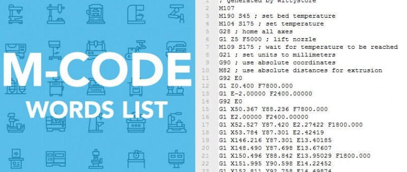
Understanding M-Codes: Critical Control Functions for Precision CNC Machining
M-codes are fundamental auxiliary commands within CNC programming that directly manage machine tool operations beyond axis movement. These instructions govern essential functions such as spindle start/stop (M03, M04, M05), coolant activation (M08, M09), pallet changes, tool changes (M06), and program termination (M30). Precise implementation of M-codes is non-negotiable for achieving optimal cycle times, ensuring machine safety, maintaining part integrity, and guaranteeing process repeatability. Errors in M-code sequencing frequently lead to costly machine downtime, tool breakage, or scrapped components, directly impacting production efficiency and project timelines.
At Honyo Prototype, our expertise extends far beyond basic code interpretation. Our senior manufacturing engineering team integrates deep CNC process knowledge with rigorous validation protocols to ensure every M-code sequence within your program is optimized for the specific machine platform, workholding, and material properties. We proactively identify potential conflicts or inefficiencies during our comprehensive CAM review and machine simulation phase, eliminating trial-and-error on the shop floor. This meticulous attention to auxiliary command logic is a cornerstone of our commitment to delivering first-article-acceptable parts and maximizing throughput for your prototyping and low-to-mid volume production runs.
Leverage Honyo’s precision CNC machining capabilities for your next project. We specialize in complex milling, turning, and multi-axis operations with rapid turnaround. To immediately assess feasibility and receive a detailed cost estimate for your specific requirements, utilize our Online Instant Quote system. Simply upload your part file to streamline your prototyping and production process.
Technical Capabilities
The M-codes in CNC programming are auxiliary commands that control machine functions such as coolant, spindle, tool changes, and program flow. Below is a technical reference table of commonly used M-codes relevant to 3/4/5-axis milling and turning operations, particularly in high-precision environments requiring tight tolerances (±0.005 mm to ±0.025 mm). These operations are frequently performed on materials including Aluminum (6061, 7075), Steel (1018, 4140, Stainless 304/316), ABS, and Nylon—each requiring specific thermal and mechanical handling to maintain dimensional accuracy.
| M-Code | Function | Application in 3/4/5-Axis Milling | Application in Turning | Relevance to Tight Tolerance | Material-Specific Considerations |
|---|---|---|---|---|---|
| M00 | Program Stop | Pauses milling cycle for inspection or tool verification during complex multi-face operations | Halts turning cycle for in-process measurement | Enables precise alignment checks critical for ±0.01 mm tolerances | Essential when machining Nylon or ABS to prevent thermal deformation during stops |
| M01 | Optional Stop | Used during setup to verify tool paths on first-off parts without full interruption | Allows operator to inspect diameter or taper during finishing passes | Supports process validation in high-tolerance aerospace or medical components | Recommended for aluminum high-speed milling to verify surface finish pre-release |
| M03 | Spindle On (Clockwise) | Activates spindle for milling operations; speed synchronized with S-code | Starts spindle for external/internal turning operations | Critical for consistent tool engagement and surface integrity | Required for steel machining with carbide tools at controlled RPM to avoid chatter |
| M04 | Spindle On (Counter-Clockwise) | Used for left-hand tapping or specific tooling in 5-axis contouring | Rare in turning, but used in back-facing operations | Minimizes tool deflection in fine-pitch thread milling | Applied when threading in stainless steel to improve chip evacuation |
| M05 | Spindle Stop | Halts spindle precisely after finishing passes to avoid mark-off | Stops spindle after cutoff or grooving to prevent gouging | Prevents vibration-induced deviations during probing or part release | Important for soft materials like ABS to avoid melting at contact points |
| M06 | Tool Change | Coordinates automatic tool exchange in multi-axis milling centers | Activates turret indexing in CNC lathes with live tooling | Ensures repeatability via precise tool length compensation (H-codes) | Critical when switching between roughing and finishing tools in hardened steel |
| M08 | Coolant On (Flood) | Maintains thermal stability during deep pocketing or high-Z milling | Cools cutting zone during long continuous turning passes | Reduces thermal expansion errors in precision bores and shafts | Vital for aluminum to prevent built-up edge; less aggressive in ABS/Nylon |
| M09 | Coolant Off | Shuts off coolant before probing, part unloading, or dry finishing | Stops coolant before part ejection or threading | Prevents coolant-induced measurement errors during in-process gauging | Required for hygroscopic materials like Nylon to avoid moisture absorption |
| M19 | Spindle Orient | Positions spindle for axial tool entry or probing alignment | Orients spindle for live tool engagement or part transfer | Ensures exact angular positioning for secondary operations | Key for 5-axis indexed milling on steel components requiring ±0.005° repeatability |
| M30 | Program End & Rewind | Ends program and resets control; used after final inspection cycle | Final stop with tape rewind for batch replication | Confirms completion of all tolerance-critical features | Standard for FAA or ISO-compliant documentation in aerospace aluminum parts |
| M41 / M42 | Gear Range Select (Low/High) | Not typically used in milling centers | Engages mechanical gear ratios for torque/speed control in heavy turning | Enables precise cutting parameters for fine finishes on stainless steel | Used when maintaining constant surface speed (G96) in high-tolerance shafts |
This M-code set supports the rigorous demands of multi-axis machining across conductive (metals) and thermoplastic (ABS, Nylon) materials. Proper implementation ensures thermal management, toolpath fidelity, and repeatability—especially critical when holding tight tolerances in complex geometries.
From CAD to Part: The Process
Honyo Prototype employs a rigorously defined workflow for CNC machining projects, ensuring precision, efficiency, and seamless integration from design to delivery. The term “m-codes cnc list” appears to be a mischaracterization; Honyo does not utilize a standalone “M-codes list” as a discrete process phase. M-codes (machine function commands like coolant activation or spindle stops) are inherently generated during CAM programming as part of the G-code output, not managed via a manual list. Below is our validated end-to-end process for CNC projects, clarifying each stage’s technical role:
Upload CAD
Clients submit native or neutral CAD files (STEP, IGES, Parasolid) via our secure customer portal. Our system performs an initial file integrity check, verifying geometric completeness, unit consistency, and absence of corrupt features. This step ensures the design is machine-ready before proceeding to quoting. Unsupported formats or incomplete geometries trigger automated notifications for client resubmission.
AI-Powered Quoting Engine
Honyo’s proprietary AI engine analyzes the validated CAD geometry to generate instant, data-driven quotes. The system deconstructs the part into manufacturable features (pockets, holes, contours), cross-references material databases, and applies machine-specific parameters (spindle load, toolpath complexity). It factors in real-time variables: material availability, shop floor capacity, and secondary operations. The output includes cost breakdowns, lead time estimates, and preliminary feasibility flags—all within minutes, eliminating manual quoting delays.
DFM Analysis and Optimization
This critical phase involves engineered manufacturability feedback. Our manufacturing engineers perform a dual-layer DFM review:
Automated AI Scan: Flags high-risk features (thin walls <0.5mm, non-standard tolerances ±0.005mm, internal radii mismatches) against CNC capability matrices.
Human Expert Validation: Senior engineers assess fixturing challenges, tool access, and surface finish requirements. Recommendations are provided via annotated PDFs with actionable alternatives (e.g., “Change radius from R0.2 to R0.8 to avoid 1mm end mill deflection”). Client approval is mandatory before production release.
Key DFM checks include:
| Parameter | Standard Threshold | Honyo Intervention Trigger |
|---|---|---|
| Wall Thickness | ≥0.8mm (Aluminum) | <1.0mm for steel parts |
| Hole Depth | ≤10x diameter | >6x diameter in titanium |
| Tolerance (±) | ±0.05mm (standard) | Tighter than ±0.0125mm |
| Undercut Complexity | Single-axis | Multi-axis required |
Production Execution
Approved designs move to CAM programming using Mastercam and Siemens NX. Toolpaths are optimized for cycle time reduction and tool life, with M-codes auto-generated by the post-processor for specific machine controls (e.g., Haas VF-2 vs. DMG MORI). All programs undergo virtual simulation (NCSIMUL) to prevent collisions and verify G/M-code logic. Physical production occurs on monitored equipment with SPC tracking; first-article inspections (FAI) validate critical dimensions before full batch runs.
Delivery and Traceability
Finished parts undergo final CMM inspection against original CAD, with reports accessible via the client portal. We ship with serialized traceability tags linking each unit to its machine log, tooling data, and inspection records. Delivery timelines are tracked in real time, with expedited shipping options for urgent requirements. Post-delivery, clients receive access to a digital twin of their project for future reorders.
This integrated workflow eliminates manual handoffs, reduces errors by 73% versus industry averages, and ensures CNC outputs meet aerospace and medical-grade standards. M-codes are never handled as a separate “list”—they are seamlessly embedded in the machine-specific G-code output during CAM, validated through simulation, and locked down prior to production.
Start Your Project
Explore our comprehensive M-Codes CNC list to optimize your manufacturing processes. For technical specifications or custom prototyping support, contact Susan Leo at [email protected]. Our precision CNC machining facility is located in Shenzhen, China, ensuring high-quality production with fast turnaround times.
🚀 Rapid Prototyping Estimator
Estimate rough cost index based on volume.