Contents
Manufacturing Insight: Linear Guide Cnc
Precision CNC Machining for Linear Guide Systems: Engineered for Performance
At Honyo Prototype, we specialize in high-accuracy CNC machining of critical linear guide components, where micron-level tolerances directly impact system rigidity, load capacity, and operational longevity. Our advanced 5-axis milling and turning centers, coupled with stringent in-process metrology, ensure linear rails, carriages, and mounting interfaces meet ISO 2768-mK or tighter specifications across materials like hardened alloy steels, stainless variants, and engineered composites. Every component undergoes thermal stability validation and surface finish verification to minimize friction coefficients and prevent premature wear in dynamic motion applications.
Our end-to-end manufacturing process integrates design-for-manufacturability analysis with secondary operations including precision grinding, hard turning, and black oxide coating—all controlled within a climate-stable facility to eliminate dimensional drift. This disciplined approach guarantees seamless integration into linear motion systems from Thomson, HIWIN, and Bosch Rexroth architectures.
Accelerate your prototyping timeline with Honyo’s Online Instant Quote platform. Upload CAD files to receive geometry-validated pricing and lead times in under 60 seconds, with DFM feedback highlighting potential cost or cycle-time optimizations. For complex linear guide assemblies requiring multi-process coordination, our engineering team provides tailored solutions from initial concept to volume production, backed by PPAP documentation and 100% first-pass yield commitments.
Partner with Honyo Prototype to transform precision motion requirements into reliably performing hardware—where engineering rigor meets rapid manufacturability.
Technical Capabilities
Linear Guide CNC Systems – Technical Specifications for 3/4/5-Axis Milling and Turning Applications
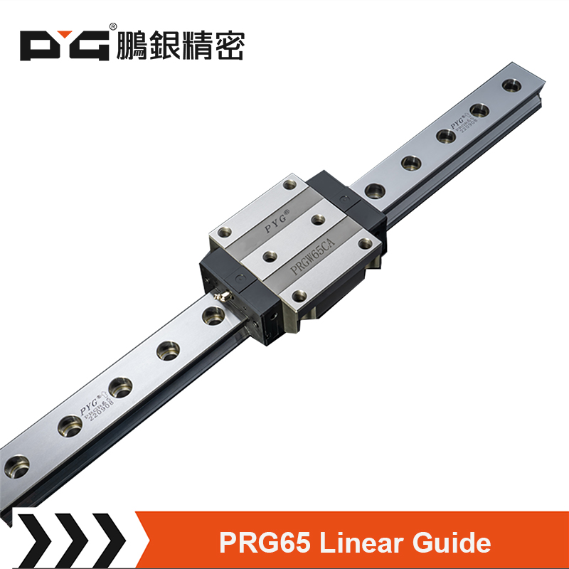
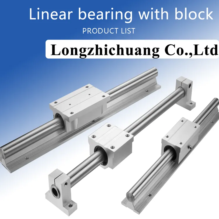
Linear guide CNC machines are engineered for high-precision machining across complex geometries, particularly in 3, 4, and 5-axis configurations. These systems utilize linear motion guides to support high rigidity, accuracy, and repeatability, making them ideal for tight-tolerance applications in industries such as aerospace, medical, and precision tooling. The following table outlines key technical specifications relevant to multi-axis milling, turning, and material compatibility with Aluminum, Steel, ABS, and Nylon.
| Parameter | Specification Description |
|---|---|
| Axes Configuration | 3-axis (XYZ), 4-axis (XYZ + A or B), 5-axis (XYZ + AB, AC, or BC) with simultaneous or indexed motion |
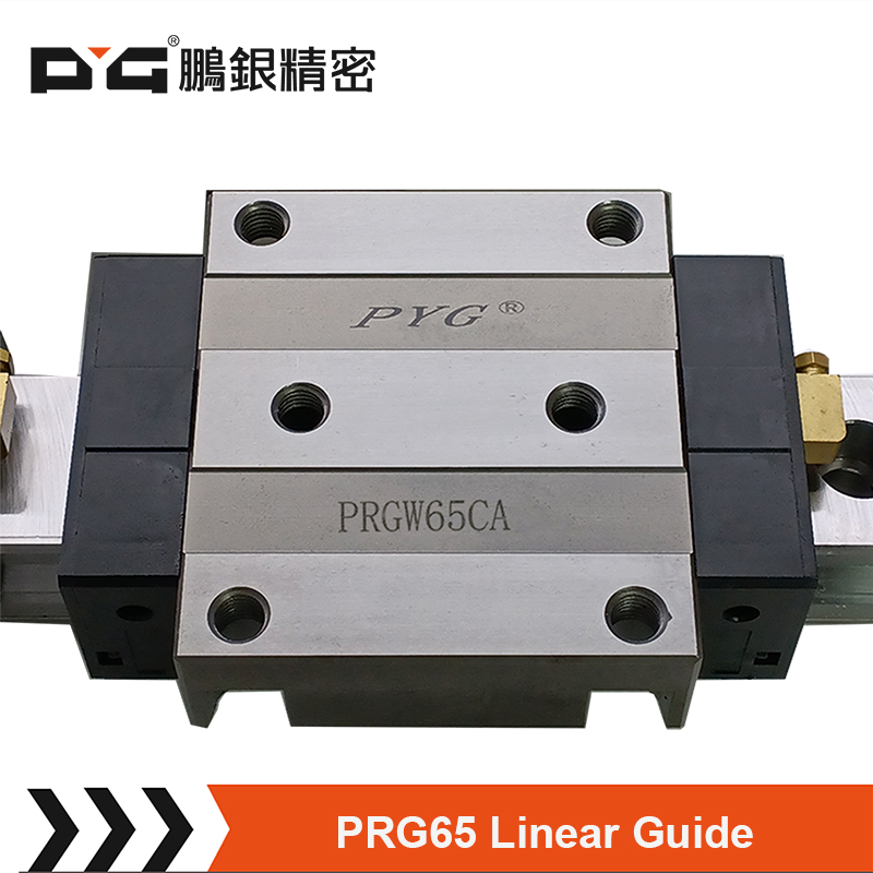
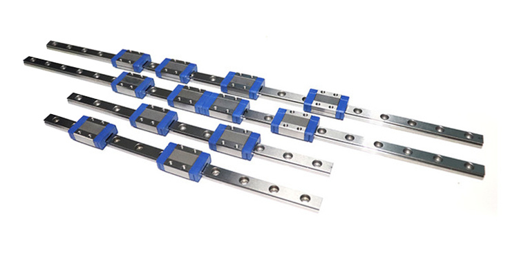
| Linear Guide Type | High-precision recirculating ball or roller linear guides (e.g., THK HSR, HIWIN QH series) |
| Guide Accuracy | ±0.005 mm/m straightness; preload classes C0 (ultra-precision) to C3 (standard) |
| Positioning Accuracy | ±0.008 mm for 3-axis; ±0.010 mm for 4/5-axis (per ISO 230-2) |
| Repeatability | ±0.003 mm typical; up to ±0.001 mm in high-end models |
| Travel Range (Typical) | X: 300–1200 mm, Y: 200–800 mm, Z: 200–600 mm; rotary axes: ±360° (A/B) with 0.001° resolution |
| Spindle Speed | 8,000–24,000 RPM (standard); up to 40,000 RPM for micromachining |
| Spindle Power | 7.5–22 kW (milling); 5–15 kW (turning) |
| Tool Changer | Automatic tool changer (ATC) with 12–30 tool capacity; optional dual-arm or carousel |
| Control System | Fanuc, Siemens, or Heidenhain with 5-axis interpolation and look-ahead functions |
| Tolerance Capability | ±0.005 mm for milling; ±0.003 mm for turning; surface finish down to Ra 0.4 µm |
| Materials Supported | Aluminum (6061, 7075), Steel (1018, 4140, Stainless 304/316), Engineering Plastics (ABS, Nylon 6/66) |
| Coolant System | High-pressure through-spindle coolant (up to 70 bar) for metal; air blast for plastics |
| Work Envelope (Example) | 800 x 500 x 400 mm (XYZ) with rotary table diameter up to 200 mm |
| Thermal Compensation | Built-in thermal sensors and real-time drift correction |
| Vibration Damping | Cast iron or polymer concrete base with active/passive damping systems |
These specifications enable linear guide CNC machines to maintain tight tolerances across diverse materials. Aluminum and steel benefit from high rigidity and coolant integration, while ABS and nylon are machined using optimized feeds/speeds and non-contact tooling strategies to prevent melting or deformation. 5-axis capabilities allow single-setup machining of complex contours, reducing cumulative error and improving dimensional consistency.
From CAD to Part: The Process
Honyo Prototype executes linear guide component manufacturing through a rigorously controlled five-stage workflow designed for precision, speed, and technical validation. This process ensures dimensional accuracy critical for linear motion systems while minimizing lead time.
CAD Upload and Validation
Clients initiate the process by uploading native or neutral CAD files (STEP/IGES preferred) via our secure portal. Our system immediately performs automated geometry validation, checking for unit consistency, closed solids, and manufacturability flags. For linear guide rails and carriages, we specifically verify critical features like ball screw mounting patterns, reference edge continuity, and hardened surface zones. Unsupported formats trigger an instant notification requesting conversion.
AI-Powered Quoting with Engineering Oversight
Proprietary AI analyzes the validated CAD model against live machine capacity, material costs, and historical process data to generate a preliminary quote within 2 hours. For linear guide components requiring tight tolerances (typically ±0.005mm on bearing surfaces), the AI flags complexity factors like grinding requirements or stress-relief cycles. A Senior Manufacturing Engineer then reviews all AI outputs, adjusting costs for precision demands such as surface roughness Ra 0.4μm specifications or geometric tolerancing (e.g., straightness ≤0.02mm/m).
Engineering-Driven DFM Analysis
Our DFM stage involves direct collaboration between the client’s design team and Honyo’s application engineers. We focus on linear motion-specific optimizations:
| DFM Check Category | Linear Guide Specific Focus | Typical Resolution |
|---|---|---|
| Material Selection | Hardened steel grade compatibility (e.g., S55C vs. SUJ2) | Recommend induction-hardened alternatives for cost reduction |
| Tolerance Stackup | Carriage-to-rail interface tolerances | Adjust non-critical dimensions to loosen GD&T where possible |
| Machining Strategy | Reference surface sequencing for grinding | Propose milling reference edges before hardening |
| Assembly Impact | Mounting hole pattern symmetry | Suggest standardized hole patterns per ISO 14728 |
This phase includes formal documentation of all proposed changes with annotated 3D markups, requiring client sign-off before proceeding.
Precision Production Execution
Approved designs move to our climate-controlled CNC facility. Linear guide rails undergo:
First, rough milling on DMG MORI 5-axis centers with coolant-through spindles to minimize thermal distortion.
Next, stress-relief heat treatment at 550°C followed by precision grinding on Studer S41 machines for critical running surfaces.
Finally, all components undergo 100% inspection via Zeiss CONTURA CMMs against ASME Y14.5 standards, with reports including straightness, flatness, and parallelism data for rail mounting surfaces. Cleanroom packaging prevents contamination of ball circuits.
Certified Delivery and Traceability
Finished components ship in custom anti-static, corrosion-inhibiting packaging with serialized traceability tags. Each shipment includes:
Material test reports (MTRs) showing hardness verification (58-62 HRC on raceways)
Full CMM inspection data correlated to CAD model datums
Conformance certificate referencing ISO 230-2 for linear accuracy
Typical delivery is 12-15 business days from DFM approval for standard configurations, with expedited options available for qualifying projects. All linear guide assemblies undergo final functional testing on our in-house motion validation rigs prior to shipment.
Start Your Project
Looking for high-precision linear guide CNC services? Contact Susan Leo at [email protected] to discuss your project requirements. Our advanced manufacturing facility in Shenzhen ensures tight tolerances, fast turnaround, and consistent quality for linear guide components. From prototyping to low-volume production, we deliver reliable CNC machining solutions tailored to your specifications. Reach out today to request a quote or technical consultation.
🚀 Rapid Prototyping Estimator
Estimate rough cost index based on volume.