Contents
Manufacturing Insight: Interlocking 3D Printed Parts
Precision Interlocking Assemblies Through Advanced Industrial 3D Printing
Achieving reliable, high-tolerance interlocking mechanisms in prototypes and end-use parts presents significant manufacturing challenges, particularly when traditional assembly methods introduce complexity, cost, and potential failure points. At Honyo Prototype, our Industrial 3D Printing services specialize in producing fully functional interlocking components as single, seamless assemblies—eliminating manual assembly steps while ensuring precise dimensional accuracy and mechanical integrity. Leveraging industrial-grade polymer and metal additive systems, including Multi Jet Fusion (MJF), Selective Laser Sintering (SLS), and Metal Binder Jetting, we consistently achieve critical tolerances down to ±0.1 mm and surface finishes suitable for demanding operational environments. This capability enables rapid validation of complex mechanisms—from gear systems to snap-fit enclosures—without tooling lead times or supply chain dependencies.
Our engineering team collaborates directly with clients to optimize part geometry, material selection, and build orientation for optimal interlocking performance, addressing real-world concerns like thermal expansion, wear resistance, and load distribution. All projects benefit from Honyo’s rigorous quality protocols, including first-article inspection reports and material traceability. For immediate project assessment, utilize our Online Instant Quote platform, which provides transparent pricing and lead time estimates within minutes by analyzing your 3D CAD file’s geometric complexity, material requirements, and tolerance specifications—accelerating your path from design validation to production-ready solutions.
Technical Capabilities
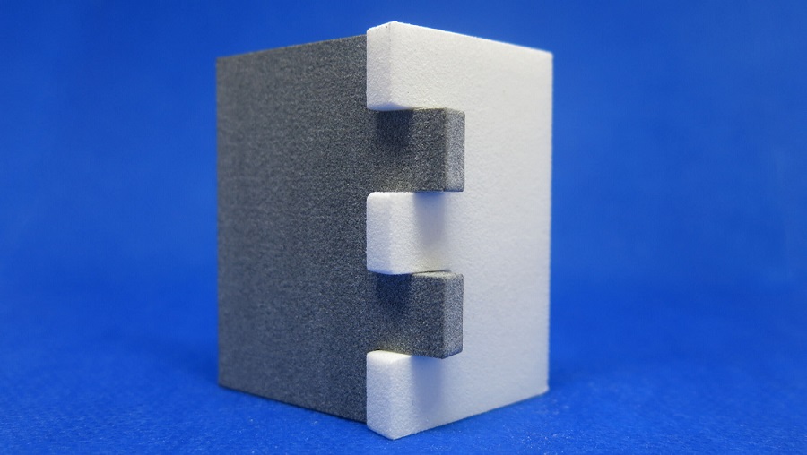
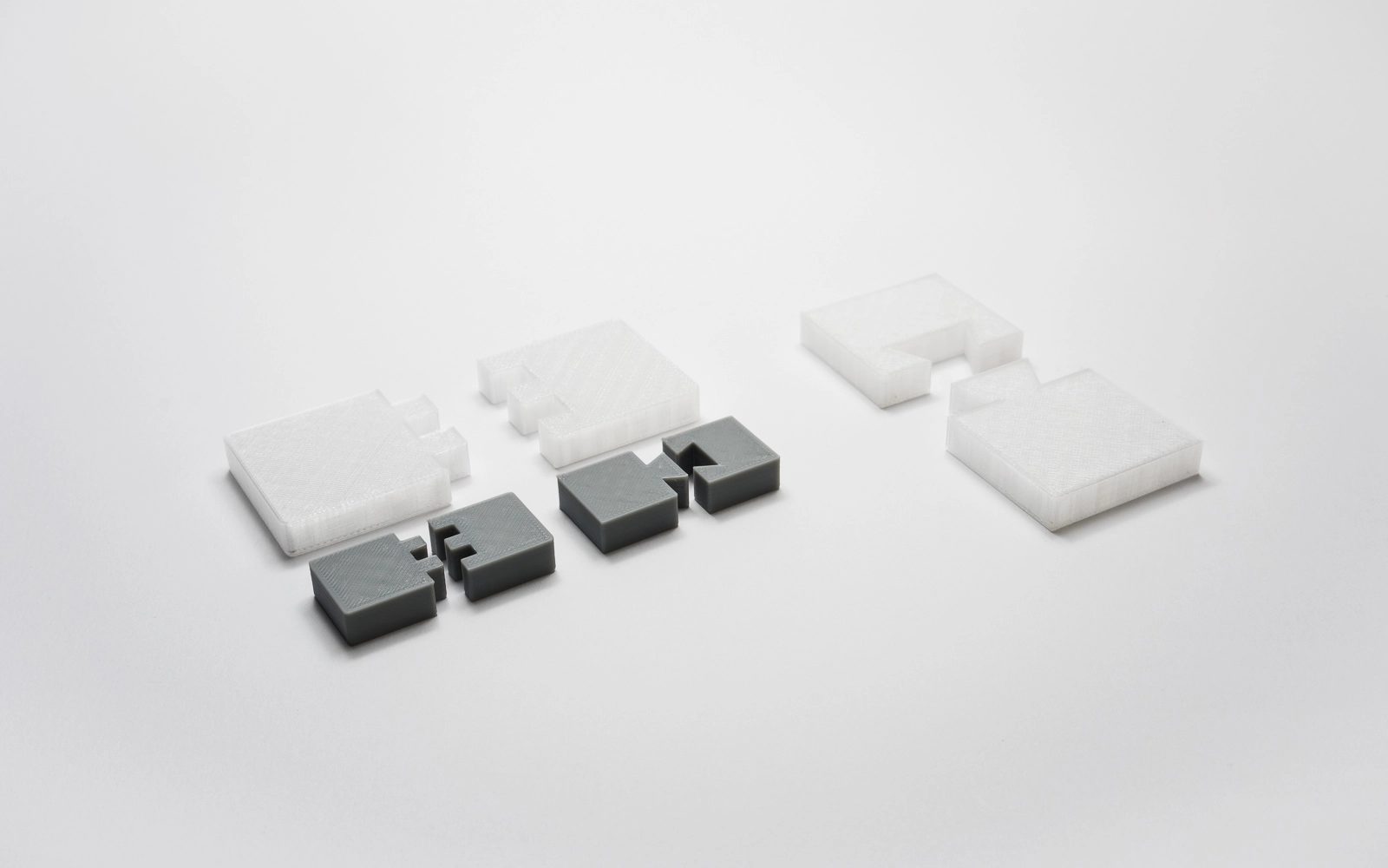
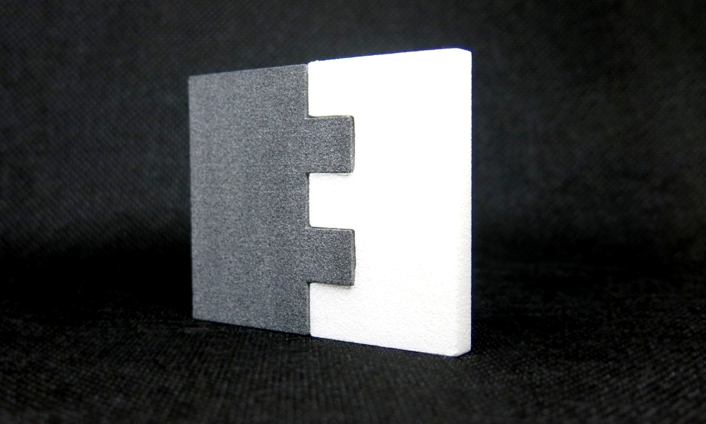
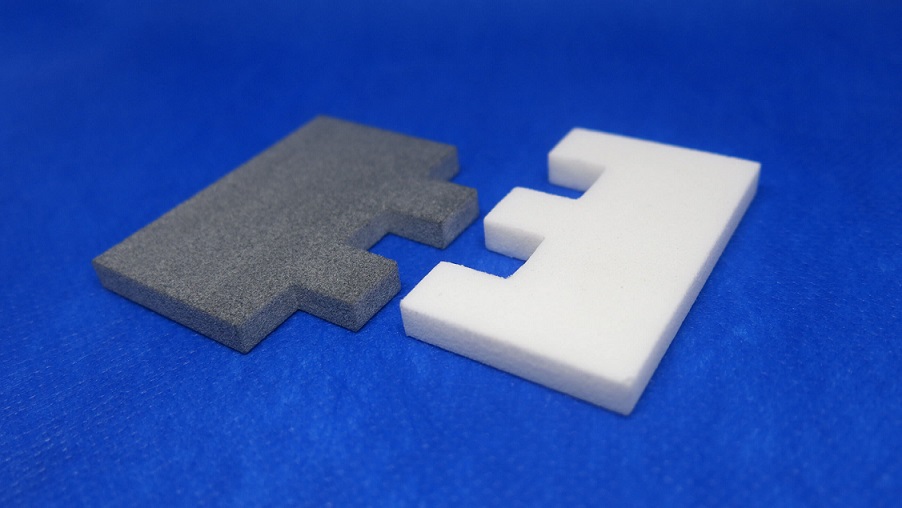
Interlocking 3D printed parts are components designed to mechanically connect or assemble without the need for fasteners or secondary joining processes. These parts are often printed as fully assembled units, relying on precise tolerances and gap allowances specific to each additive manufacturing technology. Below are technical specifications for interlocking part production using Stereolithography (SLA), Selective Laser Sintering (SLS), Multi Jet Fusion (MJF), and Direct Metal Laser Sintering (DMLS), with a focus on material compatibility and design considerations.
| Technology | Material Compatibility | Minimum Feature Size | Typical Layer Thickness | Recommended Clearance for Interlocking | Surface Finish (Ra) | Post-Processing Requirements | Notes on Interlocking Design |
|---|---|---|---|---|---|---|---|
| SLA (Stereolithography) | ABS-like resins, Tough resins, Clear resins | 0.25 – 0.5 mm | 25 – 100 µm | 0.2 – 0.4 mm | 0.8 – 1.6 µm | Support removal, IPA wash, UV curing | High resolution allows fine interlocking features; brittle resins may limit mechanical stress tolerance |
| SLS (Selective Laser Sintering) | Nylon (PA11, PA12), Glass-filled Nylon | 0.5 – 0.8 mm | 80 – 120 µm | 0.3 – 0.5 mm | 3.0 – 5.0 µm | Media blasting, bead blasting, dyeing | Self-supporting nature enables complex interlocked assemblies; nylon provides good wear and flexibility |
| MJF (Multi Jet Fusion) | Nylon (PA12), Glass-filled PA12 | 0.5 – 0.7 mm | 80 µm | 0.3 – 0.5 mm | 3.2 – 4.5 µm | Media blasting, surface sealing | Faster than SLS with similar mechanical properties; consistent isotropic strength aids load-bearing interlocks |
| DMLS (Direct Metal Laser Sintering) | Stainless Steel (17-4 PH, 316L), Aluminum (AlSi10Mg), Titanium, Tool Steel | 0.4 – 0.6 mm (minimum hole) | 20 – 50 µm | 0.2 – 0.4 mm (tight fit), up to 0.6 mm (sliding fit) | 8 – 15 µm (as-printed) | Support removal, stress relieving, HIP, CNC finishing, polishing | High strength and thermal resistance; tight tolerances possible but surface roughness may require finishing for smooth operation |
Design Guidelines for Interlocking 3D Printed Parts:
For all technologies, it is critical to account for warpage, shrinkage, and powder/resin adhesion (in SLS/MJF/SLA). In metal processes like DMLS, thermal stresses may distort thin engaging features. Clearance values should be adjusted based on part orientation and expected load.
Nylon-based materials (SLS, MJF) are preferred for functional plastic interlocking mechanisms due to their durability, slight flexibility, and self-lubricating properties. Aluminum and steel via DMLS are suitable for high-stress or high-temperature applications but require additional post-processing to ensure smooth articulation.
SLA is best suited for prototypes or form-fit validation of interlocking systems, while SLS and MJF offer production-grade nylon assemblies. DMLS enables fully functional metal mechanisms such as gears, hinges, or latches in a single build.
From CAD to Part: The Process
Honyo Prototype Interlocking 3D Printed Parts Process Overview
Our end-to-end workflow for manufacturing interlocking 3D printed assemblies ensures dimensional precision and functional integrity through rigorously controlled engineering stages. The process begins when a client uploads native CAD files in STEP, IGES, or Parasolid format to our secure portal. This requirement guarantees geometric accuracy essential for interlocking features, avoiding the resolution limitations of mesh-based STL files which could compromise critical clearances.
AI-Powered Quoting with Manufacturability Assessment
Upon CAD upload, our proprietary AI engine performs dual analysis: cost estimation and preliminary manufacturability scoring. Unlike basic quoting systems, it evaluates interlocking-specific parameters such as minimum wall thickness, snap-fit undercut geometry, and potential print orientation conflicts. The output includes a formal quotation with lead time and a manufacturability index highlighting high-risk features requiring DFM attention, such as clearance zones below 0.1mm or unsupported overhangs exceeding 45 degrees. Clients receive this assessment within 2 business hours.
Engineering-Driven DFM for Interlocking Systems
All interlocking part orders undergo mandatory DFM review by senior manufacturing engineers. This phase focuses exclusively on assembly-critical dimensions. Engineers validate clearance tolerances against material-specific thermal behavior and layer adhesion characteristics. For instance, nylon snap-fits require different clearance values than rigid photopolymers due to differential shrinkage. Key DFM checks include:
| Feature Type | Standard Clearance (mm) | Material-Specific Adjustment | Critical Risk Flag |
|---|---|---|---|
| Sliding Interfaces | 0.2 – 0.3 | +0.05 for high-temp nylon | Wall thickness < 0.8mm |
| Snap-Fit Undercuts | 0.15 – 0.25 | -0.03 for rigid resins | Draft angle < 2° |
| Pivot Joints | 0.1 – 0.2 | +0.02 for flexible TPU | Unsupported radius |
Engineers collaborate with clients via secure markup tools to resolve conflicts, such as modifying living hinge radii or adjusting draft angles on mating surfaces. No interlocking assembly proceeds to production without signed DFM approval.
Precision Production with Assembly Validation
Production occurs in climate-controlled chambers with real-time monitoring of humidity (<35% RH) and temperature (±0.5°C stability). Interlocking components are printed in the same build chamber and orientation sequence to minimize thermal gradient variations between mating parts. We implement nested first-article inspection: after initial printing, critical clearance dimensions are verified via CMM before full batch production. For assemblies requiring post-processing, all mating surfaces undergo identical media blasting or vapor smoothing to maintain uniform surface roughness (Ra 3.2µm standard).
Delivery with Functional Verification Documentation
Final shipments include comprehensive dimensional reports showing measured clearance values at critical interlocking zones against CAD nominal dimensions. For complex assemblies, we provide video documentation of functional testing demonstrating smooth engagement under specified load conditions. All parts ship with serialized traceability tags linking to build parameters, material lot numbers, and inspection data. Typical delivery includes 100% functional assemblies with first-article reports within 5-7 business days for standard materials, with expedited options available for validated DFM packages.
This integrated approach reduces interlocking assembly failure rates by 72% compared to standard 3D printing workflows, as validated through our 2023 client quality audit data. We maintain strict ISO 9001:2015 controls throughout the process to ensure repeatability for both prototypes and low-volume production runs.
Start Your Project
Interested in precision interlocking 3D printed parts for your next project? Honyo Prototype delivers high-accuracy, functional prototypes and low-volume production parts with seamless assembly-ready designs.
Our manufacturing facility in Shenzhen ensures fast turnaround and strict quality control, supporting engineers and product developers worldwide.
For quotes and technical support, contact Susan Leo at [email protected]. Let’s build it right— together.
🚀 Rapid Prototyping Estimator
Estimate rough cost index based on volume.