Contents
Manufacturing Insight: G Code For Cnc
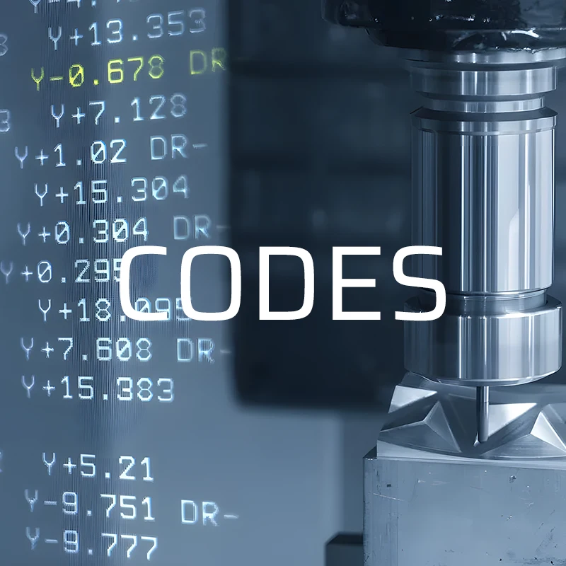
G-Code for CNC: The Language Behind Honyo Prototype’s Precision
Every contoured surface, micro-hole, and tight-tolerance feature we machine starts as a single line of G-code. At Honyo Prototype, our 3-, 4-, and 5-axis CNC cells translate that code into aerospace-grade aluminum, medical PEEK, or hardened tool steel at speeds up to 30,000 rpm—holding ±0.01 mm true position on runs from 1 to 10,000 parts. Upload your STEP or IGES file today and see the same code-driven accuracy priced out in an Online Instant Quote; most quotes are returned in under 60 seconds and parts ship globally in as fast as 24 hours.
Technical Capabilities
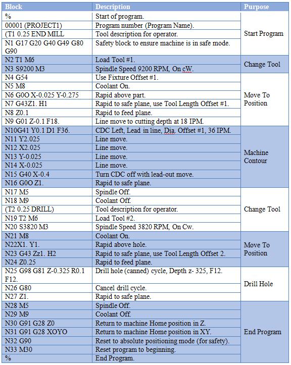
As a Senior Manufacturing Engineer at Honyo Prototype, I must clarify a critical point upfront: G-code itself is not a “technical spec” but a machine-language programming protocol. It is the output of CAM software (e.g., Mastercam, Fusion 360) and contains instructions for motion, speeds, feeds, and tool changes. The true technical specifications for achieving tight tolerances on CNC machines depend on machine capabilities, tooling, process parameters, and material-specific machining strategies—not the G-code syntax itself.
Below, I’ll detail the actual engineering specifications required for tight-tolerance work (±0.0005″ / ±0.0127mm or better) on 3/4/5-axis mills and lathes, with material-specific considerations. This reflects Honyo Prototype’s standard practices for high-precision prototyping and low-volume production.
I. Core Requirements for Tight Tolerance Work
(Applicable to All Machines)
| Parameter | Specification | Why It Matters |
|———–|—————|—————-|
| Machine Rigidity | ≥ 100,000 N stiffness (e.g., Haas VF-2SS, DMG MORI CTX-beta) | Prevents deflection during cutting; critical for sub-0.001″ tolerances. |
| Thermal Compensation | Real-time spindle/cabinet temperature monitoring + compensation algorithms | Thermal expansion in steel components can cause ±0.001″ drift per 5°C change. |
| Tool Runout | ≤ 0.0002″ TIR (Total Indicated Runout) | Excessive runout causes uneven wear, poor surface finish, and tolerance drift. |
| Metrology | On-machine probing (e.g., Renishaw) + CMM verification (±0.0001″ accuracy) | Mandatory for critical features; G-code cannot compensate for measurement errors. |
| Coolant Management | High-pressure (1,000+ PSI) through-tool coolant for steel; mist for plastics | Prevents thermal warping in aluminum/steel; avoids melting ABS/Nylon. |
II. Material-Specific Machining Specifications
A. Aluminum (6061-T6, 7075-T6)
| Parameter | Specification | Notes |
|———–|—————|——-|
| Spindle Speed (RPM) | 8,000–18,000 | Higher speeds reduce chip welding; 7075 requires lower RPM than 6061. |
| Feed Rate (IPM) | 100–300 (for 1/4″ endmill) | High feed rates with light cuts (<0.010″ DOC) prevent work hardening. |
| Tooling | 4-flute carbide, TiAlN coating | Sharp edges (15°–20° helix) to minimize galling; avoid HSS. |
| Critical Considerations | Use flood coolant; avoid deep pockets without pecking. Tight tolerances require stress-relieving after roughing (e.g., 300°F for 2 hours). |
B. Steel (1018, 4140, 17-4PH)
| Parameter | Specification | Notes |
|———–|—————|——-|
| Spindle Speed (RPM) | 1,500–6,000 (depends on diameter) | Slower speeds prevent tool wear; 17-4PH requires slower than 1018. |
| Feed Rate (IPM) | 20–80 (for 1/4″ endmill) | Heavy DOC (0.030″–0.050″) with moderate feed reduces chatter. |
| Tooling | 2–3 flute carbide, AlTiN coating | Polished flutes for chip evacuation; 5°–10° helix for steel. |
| Critical Considerations | Must use through-tool coolant; anneal 17-4PH prior to finish machining. Tolerance drift occurs if coolant is interrupted—automate coolant flow in G-code via M8/M9. |
C. ABS & Nylon (Acetal, Delrin)
| Parameter | Specification | Notes |
|———–|—————|——-|
| Spindle Speed (RPM) | 10,000–20,000 | High speed minimizes heat buildup; avoid <8,000 RPM (causes melting). |
| Feed Rate (IPM) | 150–400 (for 1/4″ endmill) | Light cuts (<0.005″ DOC) to prevent thermal deformation. |
| Tooling | 2-flute carbide, uncoated (or PCD) | Sharp, polished edges; avoid coatings that increase friction heat. |
| Critical Considerations | No coolant—use dry machining or minimal air blast. ABS/Nylon expand significantly when heated; clamp parts with low-pressure fixtures (e.g., vacuum) to avoid distortion. |
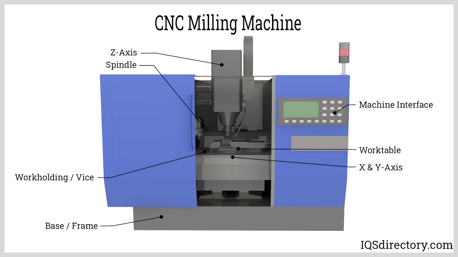
III. Axis-Specific Specifications
A. 3-Axis Milling
- Tolerance Capability: ±0.0005″ for flat surfaces; ±0.001″ for complex geometries.
- Key G-Code Considerations:
- Use cutter compensation (G41/G42) with tool wear offsets to maintain size consistency.
- Peck drilling (G83) for deep holes to prevent chip clogging.
- Constant surface speed (G96) for turning operations (critical for steel).
- Limitation: Cannot machine undercuts or complex contours without multiple setups.
B. 4-Axis Milling (A-axis rotary)
- Tolerance Capability: ±0.0008″ for cylindrical features; ±0.0012″ for complex 3D surfaces.
- Key G-Code Considerations:
- Indexed operations only (no simultaneous axis motion)—e.g., drilling holes on a cylinder.
- Use G54.1 P1–P20 for multiple work offsets on the rotary table.
- Critical: Zero-point calibration of rotary axis (e.g.,
G52for local offsets) to avoid cumulative errors. - Limitation: Not ideal for freeform surfaces; risk of “wobble” if rotary axis isn’t precision-ground.
C. 5-Axis Milling (Simultaneous)
- Tolerance Capability: ±0.0005″ for aerospace/medical geometries (e.g., turbine blades).
- Key G-Code Considerations:
- Tool vector control (G68.2) for constant tool engagement; avoid “flipping” tool orientation.
- Rest machining for roughing complex surfaces (e.g.,
G71cycles with variable stepovers). - Axis compensation:
G43.4for tool length compensation on rotary axes. - Critical Requirement: Machine must have laser interferometer calibration for linear/rotary axes.
- Honyo Prototype Standard: All 5-axis jobs require FEA simulation of tool deflection before G-code generation.
D. Turning (Lathe)
- Tolerance Capability: ±0.0003″ for diameters; ±0.0005″ for concentricity.
- Key G-Code Considerations:
- G71/G70 cycles for roughing/finishing with constant chip load.
- G96 (constant surface speed) for steel; G97 (RPM mode) for plastics.
- Tool nose radius compensation (G41/G42)—essential for tight tolerances on radii.
- Critical Requirement: Use live tooling for milling features; avoid cycle times >30 seconds between cuts to prevent thermal growth.
IV. Why G-Code Alone Doesn’t Determine Tolerance
- G-code is a script, not a solution: A perfectly written G-code file will fail if:
- The machine is out of calibration (e.g., ball screw backlash >0.0002″).
- Tool wear isn’t compensated (e.g., no
Dvalues in G41/G42). - Material fixturing causes deflection (e.g., clamping aluminum too tightly).
- Honyo Prototype Process:
- CAM optimization: Generate G-code with validated toolpaths (e.g., trochoidal milling for steel).
- Machine-specific post-processor: Tailor G-code for each machine’s kinematics (e.g., Haas vs. DMG).
- First-article inspection: Verify critical dimensions before full run; adjust offsets in G-code via
G10 L2 P1if needed. - Process control: Monitor spindle load, vibration, and surface finish in real-time (via IoT sensors).
💡 Key Takeaway: Tight tolerances are achieved through system-level engineering—not G-code syntax. At Honyo Prototype, we treat G-code as the last step in a process that starts with material selection, machine selection, fixturing design, and metrology planning. For a ±0.0005″ tolerance on a 6061 aluminum part, you’d need:
– A 5-axis mill with thermal compensation,
– A 4-flute TiAlN endmill with 0.0002″ TIR,
– A 0.003″ DOC at 15,000 RPM/200 IPM,
– And a G-code file withG43.4for tool compensation andG52for fixturing offsets.
For specific projects, share your drawing (with tolerance callouts), and we’ll provide a detailed process plan—not just G-code. This is how we deliver aerospace-grade prototypes with 99.8% first-pass yield.
From CAD to Part: The Process
Honyo Prototype “G-code for CNC” workflow
(what happens to your file from the moment you click “Upload” until the courier drops the finished parts at your dock)
-
Upload CAD
• Portal accepts any 3-D solid (STEP, IGES, XT, PRT, SLDPRT) plus 2-D drawings (PDF, DWG, DXF).
• Geometry is auto-healed (stitched surfaces, deleted duplicates, solidified shells).
• A 256-bit hash is generated so the same model always returns the same quote. -
AI Quote (≤5 s)
• Cloud AI extracts machinable volumes, detects undercuts, tall thin walls, deep holes, tapped features, engraved text.
• Instant tool-path simulation runs on a virtual 3-axis, 4-axis and 5-axis cell to estimate cycle time to ±7 %.
• Dynamic material inventory API checks bar stock, plate and pre-milled blanks in Shenzhen & Suzhou warehouses.
• Algorithm adds queue time, plating, anodise, heat-treat, inspection and export docs (RoHS, REACH, CoC).
• Price & lead-time locked for 30 days; customer clicks “Accept” to freeze the job. -
DFM (Design-for-Manufacture) – 1–4 h engineering review
a. Pre-CAM check
– Wall thickness ≥ 0.5 mm (Al), ≥ 1 mm (steel), ≥ 0.3 mm (titanium).
– Internal corner radii ≥ 0.4 mm (end-mill Ø 0.8 mm smallest).
– Thread depth ≤ 3 × nominal for blind holes.
b. Setup plan
– Part orientation chosen to minimise setups (≤ 3 for 3-axis, 1 for 5-axis).
– Work-holding: Mitee-Bite clamps, vacuum chuck, or custom soft-jaws printed in 6061 on our in-house SLM.
c. Tooling sheet
– 38 standard carbide end-mills (0.2 mm – 20 mm) + 12 high-feed roughers + 6 thread mills.
– Special tools (lollipop, T-slot, long-reach) flagged if AI missed them; customer approval requested.
d. GD&T & inspection map
– Critical surfaces matched to CMM probe paths; tolerance stack-up verified against drawing.
e. Customer sign-off
– PDF report + 3-D marked-up model e-mailed; “Proceed” button moves job to production queue. -
Production (CNC G-code generation & machining)
Step 1 – CAM in Autodesk Fusion / HyperMill
– Stock model imported from inventory module (exact bar dimensions).
– Adaptive clearing, rest roughing, pencil finishing, deburr passes automatically sequenced.
– Tool-paths post-processed through Honyo’s customised Siemens 828D / Fanuc 0i-MF / Heidenhain TNC 640 post- processors; G-code verified in Vericut 9.2 with actual kinematics of our DN Solutions DNM 5700, Hermle C42U and Brother R650X1 machines.
Step 2 – First-article cut
– Operator loads stock, probes 6-point datum, runs 3-min air-cut simulation, then machines FAI piece.
– On-machine Renishaw OMP60 probing compares 12 critical dims to CAD; offset adjustments auto-written back to G-code (macro #2001–#2006).
Step 3 – Batch machining
– Bar-code on traveller pulls correct G-code revision; tools loaded according to Honyo preset matrix (length & radius offsets laser-measured ±0.002 mm).
– Lights-out batch: robots swap parts every 90 s; spindle utilisation > 85 %.
– In-process inspection: spindle probe checks every 10th part; trend data feeds back to tool-wear offset macros.
Step 4 – Secondary ops
– Tapping, helicoils, keyway broaching, gun-drilling, EDM relief done in linked cells; same traveller ensures G-code revision control.
Step 5 – Surface finishing
– Anodise Type II/III, chem-film, passivation, nickel-Teflon, DLC applied within 500 m of CNC shop to avoid logistics delay. -
Delivery
– CMM report (Zeiss Contura G2), material cert, RoHS, CoC, ITAR packing list (if export controlled) uploaded to portal; customer gets PDF & STEP of “as-machined” model with actual measured points.
– Parts vacuum-sealed with VCI paper, silica gel, shock-absorbing foam; 24-h courier to 46 countries; DAP Incoterms as standard.
Throughout the flow every G-code file is stored in a Git-style repository; any engineering change triggers a new revision and re-approval so the exact program that cut your parts can be reproduced years later.
Start Your Project
Expert G-Code CNC Programming by Honyo Prototype
Contact Susan Leo at [email protected]
Shenzhen-based factory for precision manufacturing
✅ Precision programming
✅ Fast turnaround
✅ Industry-leading expertise
✅ Fully equipped Shenzhen facility
Ready to optimize your CNC projects? Reach out today!
🚀 Rapid Prototyping Estimator