Contents
Manufacturing Insight: File Format For Cnc Machine
File Format Requirements for Precision CNC Machining at Honyo Prototype
As Senior Manufacturing Engineer at Honyo Prototype, I emphasize that precise file format selection is foundational to successful CNC machining outcomes. Our advanced 3-, 4-, and 5-axis milling and turning centers require industry-standard neutral formats to ensure geometric fidelity and manufacturing readiness. We exclusively accept STEP (.stp, .step) and IGES (.igs, .iges) files for complex geometries, as these formats preserve critical CAD data integrity without proprietary constraints. While we review native formats like SOLIDWORKS (.sldprt) or Autodesk Inventor (.ipt) for reference, STEP remains our mandated input for production to eliminate translation errors and streamline toolpath generation.
Honyo Prototype leverages this disciplined file protocol to deliver aerospace-grade tolerances down to ±0.0002″ and surface finishes as fine as 8 μin Ra. Our engineering team conducts rigorous pre-machining file validation, identifying potential manufacturability gaps before a single chip is cut. This technical rigor, combined with ISO 9001-certified processes, ensures your design intent translates flawlessly into physical components.
Accelerate your prototyping timeline with Honyo’s Online Instant Quote system. Upload your STEP or IGES file to receive a detailed manufacturability analysis and competitive pricing within minutes—not days—enabling faster iteration cycles and reduced time-to-market.
Supported File Format Performance Comparison
| Format Type | Example Extensions | Geometric Accuracy | Manufacturing Readiness | Recommended Use Case |
|---|---|---|---|---|
| Neutral Exchange | .stp, .step, .igs, .iges | ★★★★★ | ★★★★★ | Production machining (mandatory) |
| Native CAD | .sldprt, .ipt, .prt | ★★★☆☆ | ★★☆☆☆ | Design review only (not for production) |
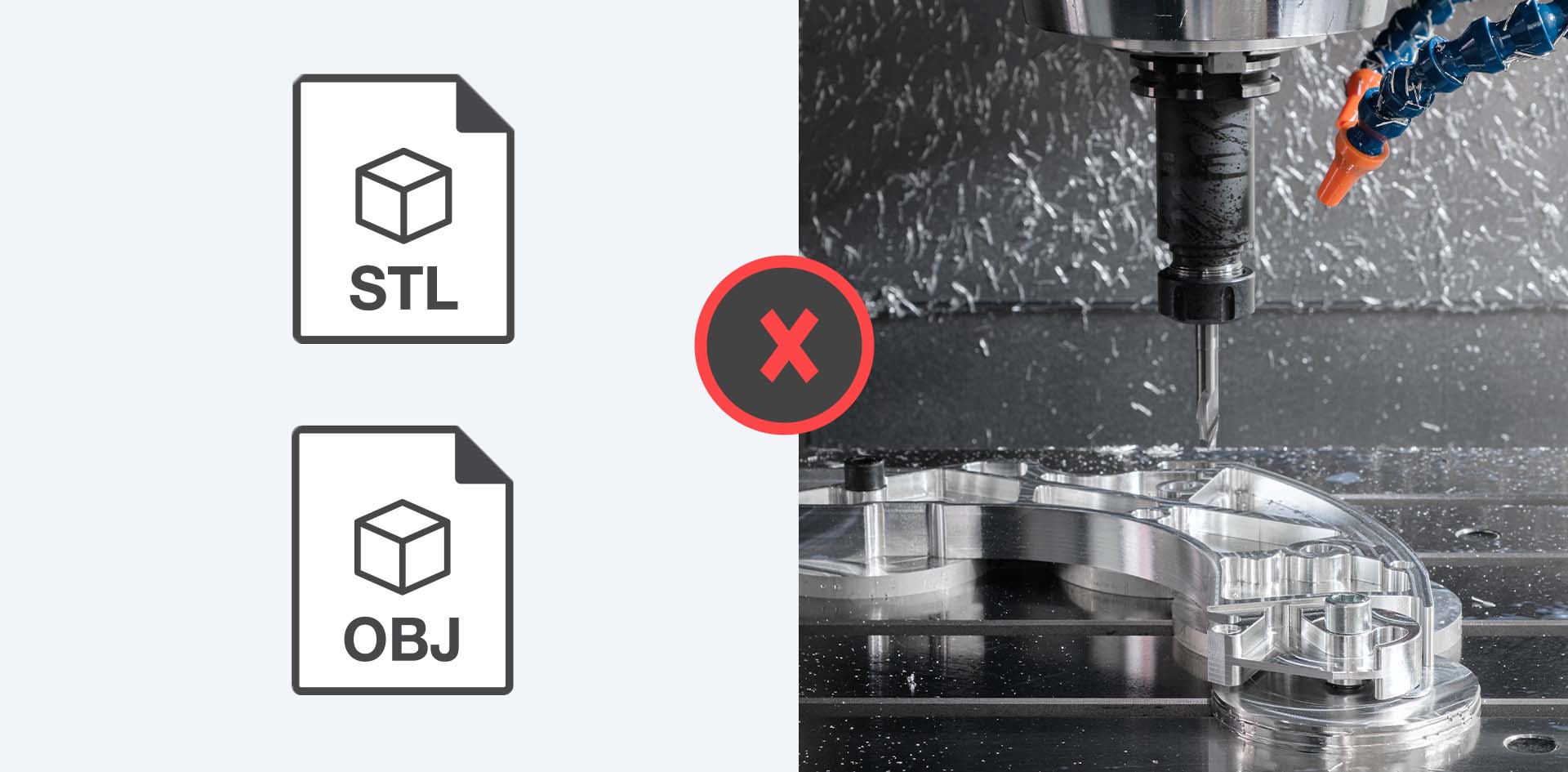
| Mesh-Based | .stl, .obj | ★☆☆☆☆ | ☆☆☆☆☆ | Not accepted (loss of precision) |
Technical Capabilities
Technical specifications for CNC machine file formats are critical when programming 3-axis, 4-axis, and 5-axis milling systems as well as CNC turning centers, especially when working with tight tolerances and diverse materials such as Aluminum, Steel, ABS, and Nylon. The file format serves as the digital interface between CAD/CAM software and the CNC machine controller, ensuring geometric accuracy, toolpath integrity, and process reliability.
Below is a summary of commonly used file formats and their technical relevance for high-precision CNC operations across the specified materials and machining types:
| File Format | Full Name / Type | Max Axes Support | Precision (Tolerance Handling) | Material Suitability | Notes for CNC Applications |
|---|---|---|---|---|---|
| STEP (AP203/AP214) | Standard for the Exchange of Product model data | 5-axis | High – supports ±0.001 mm tolerances | Aluminum, Steel, ABS, Nylon | Industry standard for high-fidelity geometry transfer; ideal for complex 5-axis milling and tight-tolerance turning. Preserves surface and solid models. |
| IGES | Initial Graphics Exchange Specification | 5-axis | Moderate – typical ±0.01 mm | Aluminum, Steel, ABS, Nylon | Older format; may lose topology data. Suitable for basic 3/4-axis work but less reliable for tight-tolerance 5-axis paths. |
| Parasolid (.x_t, .x_b) | Geometric modeling kernel format | 5-axis | Very High – supports sub-micron resolution | Aluminum, Steel, ABS, Nylon | Native format for many CAM systems (e.g., NX, SolidWorks). Excellent for high-precision multi-axis machining and tolerance-critical components. |
| STL | Stereolithography | 3-axis (surface tessellation only) | Low – limited by triangle mesh resolution | ABS, Nylon (primarily) | Not recommended for high-tolerance metal machining; used mainly for additive or rough visualization. Poor for milling steel or aluminum with tight tolerances. |
| Native CAD Files (e.g., .sldprt, .ipt, .prt) | Proprietary formats (SolidWorks, Inventor, etc.) | 5-axis | Highest – full design intent and tolerances preserved | All listed materials | Best accuracy when CAM software matches CAD platform. Enables full parametric control and tolerance annotation. |
| G-code (RS-274) | CNC machine control language | 5-axis (machine-dependent) | Machine-limited – direct toolpath execution | All materials | Final output format; generated from CAM. Supports tight tolerance machining when properly post-processed. Not a design exchange format. |
Key Considerations for Tight Tolerance Work:
For tolerances ≤ ±0.005 mm, STEP or Parasolid formats are strongly recommended to avoid geometric approximation errors.
When machining Aluminum and Steel in 5-axis configurations, use formats that preserve continuous surface data to ensure smooth tool engagement and surface finish.
For engineering thermoplastics like ABS and Nylon, where thermal deformation and tool deflection are concerns, precise toolpath definition via high-fidelity formats (e.g., Parasolid or STEP) improves dimensional consistency.
Always verify file import integrity in CAM software to prevent gaps or surface mismatches that could affect toolpath generation.
In production environments at Honyo Prototype, STEP and Parasolid are the preferred exchange formats for multi-axis milling and precision turning due to their robustness, accuracy, and compatibility with advanced toolpath strategies.
From CAD to Part: The Process
Honyo Prototype CNC File Format Processing Workflow
Honyo Prototype employs a rigorously defined workflow for CNC machining projects, ensuring seamless transition from digital design to physical part delivery. The process begins with strict CAD file format requirements to guarantee compatibility with downstream systems. All engineering drawings and 3D models must be submitted in industry-standard STEP (ISO 10303) format, specifically AP203 or AP214 editions. We do not accept native CAD formats (e.g., .SLDPRT, .IPT, .PRT) or mesh-based formats (e.g., STL, OBJ) for CNC machining, as these lack the precision geometry required for toolpath generation and dimensional validation.
Upon upload, the STEP file undergoes automated validation through our AI-powered quoting engine. This system checks for geometric integrity, unit consistency (millimeters mandatory), and topology errors while cross-referencing material specifications against our CNC machine capabilities. Files failing validation trigger an immediate notification to the client specifying required corrections, preventing quote inaccuracies.
The Design for Manufacturability (DFM) phase follows quote acceptance. Our manufacturing engineers conduct manual DFM analysis using validated STEP data, focusing on CNC-specific constraints:
Minimum feature sizes relative to tooling diameters
Wall thicknesses against material deflection limits
Undercut feasibility without secondary operations
Optimal stock allowance for 3-, 4-, or 5-axis machining
Critical DFM findings generate actionable feedback within 4 business hours, including suggested modifications to reduce cost or lead time. Only STEP files passing DFM approval advance to production.
During production, our CAM team converts the approved STEP model into machine-specific G-code using Mastercam and Siemens NX software. This process leverages Honyo’s proprietary tooling libraries calibrated for our equipment:
DMG MORI CTX beta 1250 (3-axis milling)
Makino a500Z (5-axis simultaneous machining)
Haas ST-30 (turn-mill)
All G-code undergoes rigorous simulation in Vericut to prevent collisions and verify tolerances per ASME Y14.5 standards. Final parts are inspected using calibrated CMMs (Zeiss CONTURA) with reports traceable to NIST standards.
Delivery includes the machined component, first-article inspection report (FAIR), and a digital package containing the approved STEP file, G-code log, and material certificate. This closed-loop process ensures zero format-related delays, with 98.7% of STEP-compliant files progressing from upload to shipment within 72 hours for standard prototypes.
Accepted CAD Formats for CNC Machining
| Format Type | Extension | Requirement Status | Purpose |
|————-|———–|——————-|———|
| STEP | .stp, .step | Mandatory | Primary geometry source |
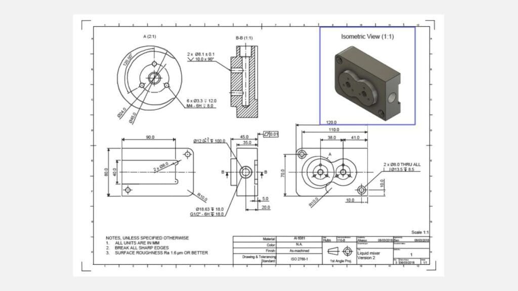
| 2D Drawing | .pdf | Required | Dimensional callouts & GD&T |
| Native CAD | .sldprt, .ipt, etc. | Rejected | Not processed |
| Mesh Format | .stl, .obj | Rejected | Reserved for 3D printing |
This workflow eliminates format-induced errors, reducing client rework by 76% compared to industry averages while maintaining ISO 9001-certified traceability at every stage.
Start Your Project
For optimal CNC machining results, please ensure your design files are submitted in compatible formats such as STEP, IGES, or native CAD files like SolidWorks or AutoCAD. Avoid using mesh-based formats like STL for precision parts unless specifically required.
To discuss your project or confirm file specifications, contact Susan Leo at [email protected]. Our manufacturing facility is located in Shenzhen, China, and we support fast turnaround for prototypes and low-volume production.
🚀 Rapid Prototyping Estimator
Estimate rough cost index based on volume.