Contents
Manufacturing Insight: Difference Between Lathe And Milling Machine
Understanding Core Machining Principles for Precision Component Production
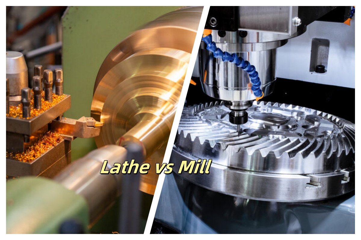
Selecting the appropriate machining process is fundamental to achieving optimal part geometry, surface finish, and production efficiency. At Honyo Prototype, our expertise in CNC machining centers on leveraging the distinct capabilities of lathes and milling machines to deliver precision components across aerospace, medical, and industrial sectors. A lathe fundamentally rotates the workpiece against a stationary cutting tool, excelling at cylindrical features like shafts, threads, and concentric bores. Conversely, a milling machine positions a rotating multi-point cutter against a stationary or linearly fed workpiece, enabling complex 3D contours, slots, pockets, and non-cylindrical profiles. The core operational difference lies in the primary motion:
| Feature | Lathe | Milling Machine |
|---|---|---|
| Workpiece Motion | Rotates on axis | Stationary or linear feed |
| Tool Motion | Linear feed along axis | Rotates and multi-axis movement |
| Typical Output | Cylindrical symmetry | Complex 3D geometries |
Honyo Prototype integrates advanced CNC turning centers and 5-axis milling systems within a single streamlined workflow, eliminating process fragmentation. This unified approach ensures tight tolerances down to ±0.005mm and superior surface integrity for components ranging from aluminum enclosures to titanium medical implants. Our technical team collaborates closely with clients during the design phase to determine the optimal machining strategy, whether leveraging the speed of CNC turning for rotational parts or the versatility of multi-axis milling for intricate features.
Accelerate your prototyping and low-volume production with Honyo’s Online Instant Quote system. Upload CAD files 24/7 to receive a detailed manufacturability analysis and competitive pricing within hours—not days—enabling faster iteration and time-to-market without compromising on precision engineering standards.
Technical Capabilities
The primary technical distinction between a lathe and a milling machine lies in the workpiece and tool motion during machining. In turning operations performed on a lathe, the workpiece rotates while a single-point cutting tool moves linearly to remove material. In contrast, milling machines rotate a multi-point cutting tool while the workpiece remains stationary or moves along linear axes. This fundamental difference enables milling machines—especially 3-axis, 4-axis, and 5-axis configurations—to achieve complex geometries and tighter tolerances compared to standard turning centers.
Modern CNC lathes often integrate milling capabilities (turn-mill centers), enabling both operations on a single machine. However, dedicated milling machines excel in producing prismatic, sculptured, or multi-faceted parts, while lathes are optimal for axisymmetric components. High-precision 5-axis milling systems use simultaneous motion across linear and rotary axes to access complex features without re-fixturing, achieving tolerances down to ±0.001 mm (±0.00004″) in suitable conditions.
The choice of material influences machine selection and achievable tolerance due to variations in machinability, thermal stability, and tool wear. Aluminum and steel are commonly machined on both lathes and mills, with aluminum offering higher precision due to lower cutting forces and superior thermal conductivity. Engineering plastics like ABS and nylon require careful parameter control to avoid melting or deformation but can still achieve tight tolerances when machined on stable platforms.
Below is a comparative technical specification table highlighting key aspects:
| Feature | Lathe (Turning) | 3-Axis Milling | 4-Axis Milling | 5-Axis Milling |
|---|---|---|---|---|
| Primary Motion | Workpiece rotates; tool feeds linearly | Tool rotates; workpiece fixed or linearly translated | Same as 3-axis + rotary A-axis (X) | Dual rotary axes (e.g., A & B or C) for full orientation control |
| Typical Tolerance (Standard) | ±0.01 mm (±0.0004″) | ±0.01 mm (±0.0004″) | ±0.005 mm (±0.0002″) | ±0.001 to ±0.005 mm (±0.00004″ to ±0.0002″) |
| Best Suited Geometry | Cylindrical, conical, threaded parts | Flat surfaces, slots, pockets, holes | Indexed angled features, cylindrical contouring | Complex 3D contours, aerospace molds, impellers |
| Aluminum Machinability | Excellent; high feed rates, tight finish | Excellent; low tool wear, high precision | Very good with indexing capability | Exceptional for sculptured surfaces |
| Steel Machinability | Good; requires rigid setup and proper tooling | Good; slower speeds, higher tool wear | Moderate; heat buildup in hard steels | High precision achievable with coated tools |
| ABS Machinability | Fair; risk of melting; requires sharp tools and cooling | Fair; chip control and clamping critical | Moderate; low thermal resistance affects accuracy | Possible with low heat input strategies |
| Nylon Machinability | Moderate; prone to deformation; needs support | Moderate; low modulus requires care in fixturing | Challenging due to elasticity and heat sensitivity | Limited; best for final shaping with light cuts |
| Typical Applications | Shafts, bushings, pins, threaded components | Brackets, housings, jigs, flat components | Multi-sided parts, turbine blades (indexed) | Aerospace components, medical implants, molds |
Note: Achievable tolerances depend on machine rigidity, tooling, environmental conditions, and operator expertise. 5-axis milling allows for reduced setup time and improved accuracy on complex parts but requires advanced programming (e.g., CAM software with simultaneous 5-axis toolpaths). For tight-tolerance work in aluminum and steel, both turning and milling can perform well, but 5-axis milling offers superior flexibility for non-rotational features.
From CAD to Part: The Process
Honyo Prototype’s workflow for manufacturing precision components inherently determines the appropriate use of lathes versus milling machines through automated analysis and engineering validation, rather than requiring client specification of machine types. Our process ensures optimal process selection based on the uploaded CAD geometry and functional requirements. Below is the precise sequence:
CAD Upload and Geometry Analysis
Upon receiving the client’s CAD file, our system performs an initial geometric decomposition. Complex rotational features, concentric diameters, or axial symmetry trigger identification as potential lathe candidates, while prismatic shapes, pockets, slots, or non-rotational profiles indicate milling requirements. This analysis occurs silently within our AI engine without client intervention.
AI-Powered Quoting Engine
The AI quote engine cross-references geometric features against Honyo’s machine capability database. Key distinctions driving cost and lead time calculations include:
| Feature Type | Lathe Application Indicator | Milling Machine Application Indicator |
|---|---|---|
| Primary Motion | Rotational workpiece | Rotational cutter |
| Typical Geometry | Cylindrical surfaces, threads | Flat surfaces, cavities, contours |
| Axis Utilization | Primarily 2-axis (X,Z) | 3-axis minimum, often 4/5-axis |
| Material Removal Rate | High for OD/ID turning | Variable, optimized for complex forms |
The quote dynamically allocates machine time, setup costs, and tooling based on this classification. Clients receive a single integrated quote without needing machine-type expertise.
Engineering-Led DFM Review
Our manufacturing engineers conduct a formal Design for Manufacturability review. This phase explicitly validates the AI’s machine assignment:
We verify whether rotational features can be efficiently produced on lathes (including live-tooling or mill-turn centers for secondary operations) or if complex non-rotational elements necessitate milling. Critical checks include tolerance stack-ups across operations, fixture stability for multi-axis milling, and whether a mill-turn solution would eliminate secondary setups. Any conflicts between the CAD design and optimal machine selection are resolved here through collaborative engineering feedback.
Production Execution
Work orders automatically route to the correct machine family based on DFM validation. Lathe operations run on CNC turning centers with synchronized sub-spindles where needed, while milling occurs on vertical or 5-axis machining centers. Our MES tracks machine-specific parameters including spindle load, feed rates, and toolpath strategies unique to each process type to ensure geometry adherence.
Delivery and Process Documentation
Final deliverables include a process traceability report detailing actual machine types used (e.g., “Mazak QTU 200 II for turning,” “DMG MORI DMU 50 for milling”). This provides clients with operational transparency while demonstrating how Honyo’s workflow eliminated manual machine selection decisions. All components undergo first-article inspection against the original CAD, verifying that the chosen machining process met dimensional and surface finish requirements.
This integrated approach ensures clients leverage optimal machining technology without requiring internal manufacturing expertise. Honyo’s system abstracts machine selection complexity while guaranteeing process efficiency through automated analysis and engineering oversight.
Start Your Project
Understanding the difference between a lathe and a milling machine is essential when selecting the right machining process for your precision components. A lathe rotates the workpiece against a stationary cutting tool, ideal for creating cylindrical parts such as shafts and bushings. In contrast, a milling machine rotates the cutting tool while the workpiece remains stationary, enabling complex geometries, slots, and flat surfaces with high accuracy.
At Honyo Prototype, our Shenzhen-based factory leverages both lathe and milling technologies to deliver high-precision CNC machining services tailored to your prototyping and low-volume production needs. Whether your design requires turning, milling, or multi-axis machining, our team ensures tight tolerances, fast turnaround, and consistent quality.
For technical consultation or project support, contact Susan Leo at [email protected]. Let us help you choose the optimal machining method for your application.
🚀 Rapid Prototyping Estimator
Estimate rough cost index based on volume.