Contents
Manufacturing Insight: Definition Of Cnc Machining
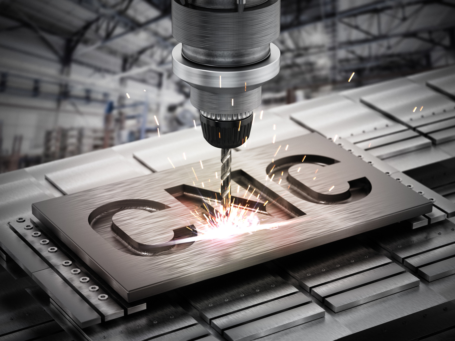
Definition of CNC Machining – and why it starts with a Honyo mouse-click
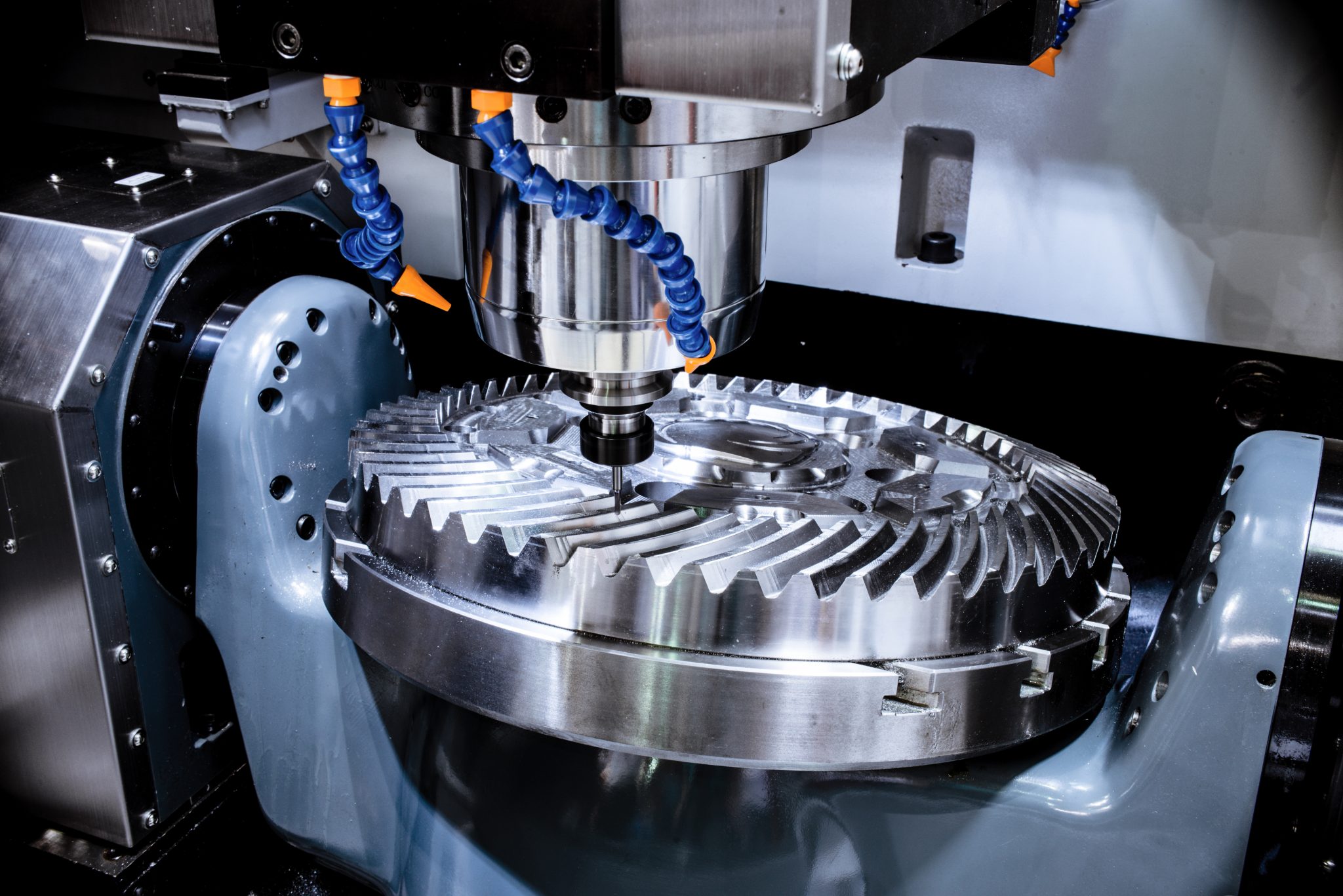
CNC (Computer Numerical Control) machining is the subtractive manufacturing process in which pre-programmed software dictates the movement of multi-axis mills, lathes, EDM and grinding equipment to turn raw material into a finished part with micron-level accuracy. At Honyo Prototype we’ve spent the last 15 years refining that definition into one sentence for our customers: upload a file, get an Online Instant Quote in under 60 seconds, and watch your design become a precision-machined reality in as fast as 24 hours. Whether you need a single aerospace-grade aluminum bracket or a 5-axis titanium surgical component, Honyo’s CNC Machining services deliver tolerances down to ±0.01 mm, full material traceability, and production scalability—without ever leaving your browser.
Technical Capabilities
Technical Specifications Overview: CNC Machining Capabilities at Honyo Prototype
(As Senior Manufacturing Engineer, Honyo Prototype)
Clarification: “CNC machining” is not a single technical spec—it’s a process defined by computer-controlled subtractive manufacturing. Below, I detail the practical engineering specifications for key capabilities at Honyo Prototype, based on real-world machine capabilities, material behaviors, and quality standards. These specs are critical for prototyping and low-volume production.
1. Core CNC Machining Principles
- Definition: A subtractive manufacturing process where computer-controlled cutting tools remove material from a workpiece to create geometries defined by CAD/CAM software.
- Key Output: Precision-engineered parts with consistent dimensional accuracy, surface finish, and repeatability.
- Honyo’s Focus: Optimizing for prototyping agility (24–72h turnaround) and production-ready quality, balancing cost, lead time, and technical feasibility.
2. Axis Capability Specifications
(Machine Examples: Haas VF-2SS (3-axis), DMG MORI CTX-beta 500 (5-axis), Okuma MB-46V (Turning))
| Axis Type | Key Technical Specs | Typical Applications at Honyo | Limitations & Considerations |
|———–|————————————————————————————|———————————————————————————————-|———————————————————————————————-|
| 3-Axis Milling | • X, Y, Z linear movement only
• Max travel: 30″ x 20″ x 20″
• Positional accuracy: ±0.0005″ (ISO 230-2)
• Repeatability: ±0.0002″ | Simple prismatic parts, flat surfaces, pockets, holes
(e.g., brackets, enclosures, jigs) | • Complex geometries require multiple setups → longer lead time
• Risk of misalignment between setups |
| 4-Axis Milling | • Adds rotary A-axis (0°–360°)
• Max rotary speed: 100 RPM
• Tilt accuracy: ±0.01°
• Surface finish: Ra 0.8μm achievable | Cylindrical features with features on sides
(e.g., pump housings, valve bodies with helical threads) | • Requires specialized fixturing
• Tool path complexity increases programming time |
| 5-Axis Milling | • Simultaneous X/Y/Z + A/B rotation
• Max tilt angle: ±110° (B-axis)
• Positional accuracy: ±0.0003″
• Surface finish: Ra 0.4μm achievable | Complex aerospace/medical geometries, impellers, freeform surfaces
(e.g., turbine blades, dental implants) | • 30–50% higher cost than 3-axis
• Requires advanced CAM software & skilled programmers
• Not always necessary—used only when required for geometry or setup reduction |
Honyo Insight: We avoid 5-axis for simple parts—3-axis with optimized fixturing is often faster and more cost-effective. 5-axis is reserved for parts where single-setup complexity (e.g., undercuts, contoured surfaces) justifies the investment.
3. Turning Specifications
(Machine Examples: Okuma LB3000 EX, Doosan Puma 2600)
– Max Part Diameter: 6″ (150mm)
– Max Part Length: 24″ (600mm)
– Tolerance Control:
– Roundness: ≤0.0005″
– Straightness: ≤0.001″ per inch of length
– Surface finish: Ra 0.8–1.6μm standard; Ra 0.4 achievable with fine finishing tools
– Live Tooling Capability: Milling/drilling on turning centers (e.g., cross-drilled holes, slots).
– Typical Applications: Shafts, bushings, flanges, threaded components.
– Critical Note: Thermal expansion during high-speed turning affects tolerances for steel—coolant flow must be optimized to maintain ±0.0005″ on critical diameters.
4. Tight Tolerance Engineering Standards
(All tolerances assume proper fixturing, material stability, and validated process)
| Tolerance Tier | Standard (Typical) | Tight (Specialized) | Critical (Requires Special Process) | Key Influencing Factors |
|—————-|——————-|———————|————————————|————————-|
| Dimensional | ±0.005″ (±0.13mm) | ±0.001″ (±0.025mm) | ±0.0005″ (±0.013mm) | • Material thermal expansion
• Machine calibration (daily)
• Fixturing rigidity
• Tool wear compensation |
| Geometric | Position: ±0.005″
Flatness: 0.002″ | Position: ±0.001″
Flatness: 0.0005″ | Position: ±0.0005″
Flatness: 0.0002″ | • Vibration control
• Temperature-controlled room (±2°C)
• In-process measurement (CMM) |
| Surface Finish | Ra 1.6μm (63μin) | Ra 0.8μm (32μin) | Ra 0.4μm (16μin) | • Tool geometry (sharpness, radius)
• Feed rate optimization
• Chip evacuation |
Honyo Reality Check:
– “Tight tolerance” is relative to part size. A ±0.001″ tolerance on a 10mm part is extremely tight; on a 100mm part, it’s routine.
– We never guarantee tolerances without reviewing the full part drawing—material, geometry, and feature relationships dictate feasibility.
– For ±0.0005″ tolerances, we require:
– CMM verification of first article
– Process capability studies (Cpk ≥1.67)
– Dedicated machine cleaning/calibration before run
5. Material-Specific Machining Specs
(All specs assume standard Honyo tooling and processes; adjustments made per part requirements)
| Material | Typical Tolerances | Key Machining Challenges | Honyo Process Recommendations | Common Applications |
|———-|——————-|————————-|——————————|———————|
| Aluminum (6061-T6, 7075) | • ±0.005″ standard
• ±0.001″ tight | • Thermal expansion → warpage
• Built-up edge (BUE) with dull tools
• Chip evacuation critical | • Sharp carbide tools (4-flute)
• High-speed cutting (1000+ SFM)
• Flood coolant (water-soluble)
• Stress-relief annealing for large parts | Aerospace brackets, heat sinks, enclosures |
| Steel (1018, 4140, 304SS) | • ±0.005″ standard
• ±0.001″ tight | • Tool wear (harder materials)
• Heat generation → distortion
• Stainless steel galling | • Carbide with TiAlN coating
• Moderate speeds (150–300 SFM)
• High-pressure coolant
• Peck drilling for deep holes | Jigs, fixtures, structural components |
| ABS (Acrylonitrile Butadiene Styrene) | • ±0.010″ standard
• ±0.005″ tight | • Melting at high temps
• Thermal warpage during cooling
• Tool chatter due to low stiffness | • Sharp HSS tools (slow speeds: 50–100 SFM)
• No coolant (air blast only)
• Clamping force < 10 lbs
• Post-machining stress relief (50°C oven) | Functional prototypes, enclosures, automotive trim |
| Nylon (6/6, 6/12) | • ±0.010″ standard
• ±0.005″ tight | • Moisture absorption → dimensional drift
• Very low melting point
• Stringy chips | • Very slow speeds (30–80 SFM)
• Dry machining (no coolant)
• Sharp tools with positive rake
• Immediate drying after machining | Gears, bearings, electrical components |
Critical Material Notes from Honyo:
– Plastics (ABS/Nylon): Tolerances are highly dependent on humidity control. We store materials in dry cabinets and machine within 24h of opening.
– Steel vs. Aluminum: Steel requires slower speeds but achieves tighter tolerances than aluminum for the same part geometry due to lower thermal expansion.
– Always specify material grade—e.g., “6061-T6” vs. “6061-O” changes machining behavior significantly.
Honyo Prototype’s Commitment to Technical Rigor
- Process Validation: Every job includes a First Article Inspection Report (FAIR) with CMM data for critical tolerances.
- Design for Manufacturability (DFM): We proactively review CAD files for tolerance feasibility—e.g., “A ±0.001″ tolerance on a 0.020″ thin wall is unrealistic; consider increasing wall thickness.”
- Why This Matters: At Honyo, we don’t just meet specs—we engineer how to meet them cost-effectively. For prototyping, we often relax tolerances where possible to accelerate delivery. For production parts, we validate processes to ensure consistency.
Pro Tip for Clients: Share your part’s functional requirements (e.g., “This hole must align to ±0.001″ to mate with a bearing”)—not just the drawing. This lets us optimize the process instead of applying unnecessary tight tolerances everywhere.
For a specific project, send us your CAD file and functional specs—we’ll provide a detailed machining plan with tolerances, tooling, and lead time within 24 hours.
— Senior Manufacturing Engineer, Honyo Prototype
Precision Prototyping Since 2010
From CAD to Part: The Process
Honyo Prototype – “Definition of CNC Machining” Workflow
(what we mean when we say “CNC machining” inside our four walls)
-
Upload CAD
• Customer drops any mix of .step, .iges, .x_t, .sldprt, .3mf or native Catia/NX files into the portal (or e-mails the secure link).
• System immediately checksums the file, runs a topology heal (knit gaps, remove zero-thickness faces, duplicate body check) and creates a SHA-256 “digital twin” ID that follows the job forever.
• A lightweight Web-GL model is pushed back to the customer so they can spin the part and confirm we opened exactly what they intended—this is the first gate in our “definition”. -
AI Quote (30 s – 5 min)
• The AI classifier decides whether the geometry is 3-axis, 3+2, 5-axis, mill-turn, or live-tool lathe.
• A CNN trained on 1.2 M historical cycles predicts cycle time per setup by voxelising the part at 0.2 mm resolution and “imagining” tool paths.
• Stock estimator adds 1 – 3 mm per side depending on predicted deflection; blank cost is pulled from real-time LME aluminium, 304/316L, Ti-6-4, POM, PEEK rod/bar pricing.
• Tolerance engine reads the PMI; any ≥ IT7 or GD&T call-outs automatically trigger CMM hours and micro-finishing ops.
• A risk score (0 – 100) is generated: thin walls, deep pockets, undercuts, tool-length-to-diameter ratio > 7, etc. If risk > 70 the quote is routed to a human application engineer for confirmation—otherwise the price is frozen and displayed instantly.
• Lead-time algorithm looks at open machine hours across 3 factories, then locks a calendar date (e.g., “Parts ship 09-June 17:00”).
• The customer clicks “Accept”; the quote becomes the legally binding specification revision 0. -
DFM (Design-for-Manufacture) – “Free in 24 h, Worth Every Penny”
• A senior manufacturing engineer (that’s me) opens the digital twin in our CAM stack (NX + HyperMill).
• We do a formal “definition of CNC machining” review:
– Machining sequence: rough, semi-finish, finish, deburr, any wire/EDM, surface treatment.
– Work-holding: we model soft-jaw geometry, vacuum chuck or fixture plate and run FEA clamp-force to ensure ≤ 20 µm deflection.
– Tool list: carbide grade, coating, L:D ratio, expected tool life; if a tool is < 0.3 mm diameter we flag it as “consumable” and stock 5 spares.
– Tolerance stack-up: we map every GD&T call-out to an operation and a gauging method (on-machine probing or CMM).
– Cost-reduction ideas: turn a 5-axis job into 3+2, combine parts in a tombstone, suggest radii that match standard end-mills.
• A 2-page DFM PDF + colour tool-path images is sent to the customer; we ask for e-signature or revision. No material is ordered until DFM is signed—this prevents “oops” moments and is the second critical definition gate. -
Production – “What we actually do to the metal”
a. Prep & Program
• CAM posts G-code with Honyo macros: tool-break detection, in-cycle probing, automatic tool-life countdown.
• First-article inspection (FAI) programme is written in PC-DMIS and uploaded to the CMM.
b. Material & Setup
• Bar stock or plate is laser-etched with the digital twin ID; photo recorded.
• Fixture is qualified on a Renishaw spindle probe; datum is set to ≤ 5 µm repeatability.
c. Cut
• Parts run on Brother Speedio 3-axis cells, DMG MORI 5-axis mill-turns, or Hyundai-Kia turning centres depending on the AI routing.
• In-cycle probing updates wear offsets every 3rd part; data is logged to MQTT broker for SPC dashboards.
d. Quality
• 100 % dimensional on first article; AQL 1.0 on subsequent articles.
• Critical features (≥ IT6) get 100 % CMM verification; others checked with Trimos height gauge or micrometres.
• Surface finish (Ra) verified by Mitutoyo SJ-210; anodise, chem-film, passivation outsourced to audited suppliers.
e. Finishing & Assembly
• Deburr under 10× magnification, ultrasonically clean, apply rust inhibitor, laser-mark revision & serial number.
• If “assembly” was quoted we install helicoils, PEM inserts, or do dry-film lube here. -
Delivery – “Arrive exactly when we promised”
• Parts are vacuum-sealed with VCI paper, boxed with custom CNC-cut foam that matches the part envelope (we reuse off-cut MDF—zero single-use plastic).
• DHL, FedEx or UPS label auto-generated from the original quote; tracking number is pushed back to the portal and customer’s ERP via webhook.
• Digital traveller package (PDF + native QC data) is uploaded; customer can download CMM reports, material certs, RoHS/REACH, CoC before the box even lands.
• 30-day feedback loop: if any deviation is reported we open an 8D, update the AI training set, and lock the corrective action to the digital twin so the next quote self-corrects.
That end-to-end chain—CAD ➜ AI Quote ➜ DFM ➜ Production ➜ Delivery—is what we internally call the “Definition of CNC Machining” at Honyo Prototype: a fully digital, closed-loop process that turns a screen-full of pixels into inspected, packaged, on-time metal parts.
Start Your Project
Ready to transform your designs into precision parts? Contact Susan Leo at [email protected] to discuss your CNC machining project. Our Shenzhen-based factory delivers unmatched quality, speed, and expertise. 🛠️
🚀 Rapid Prototyping Estimator