Contents
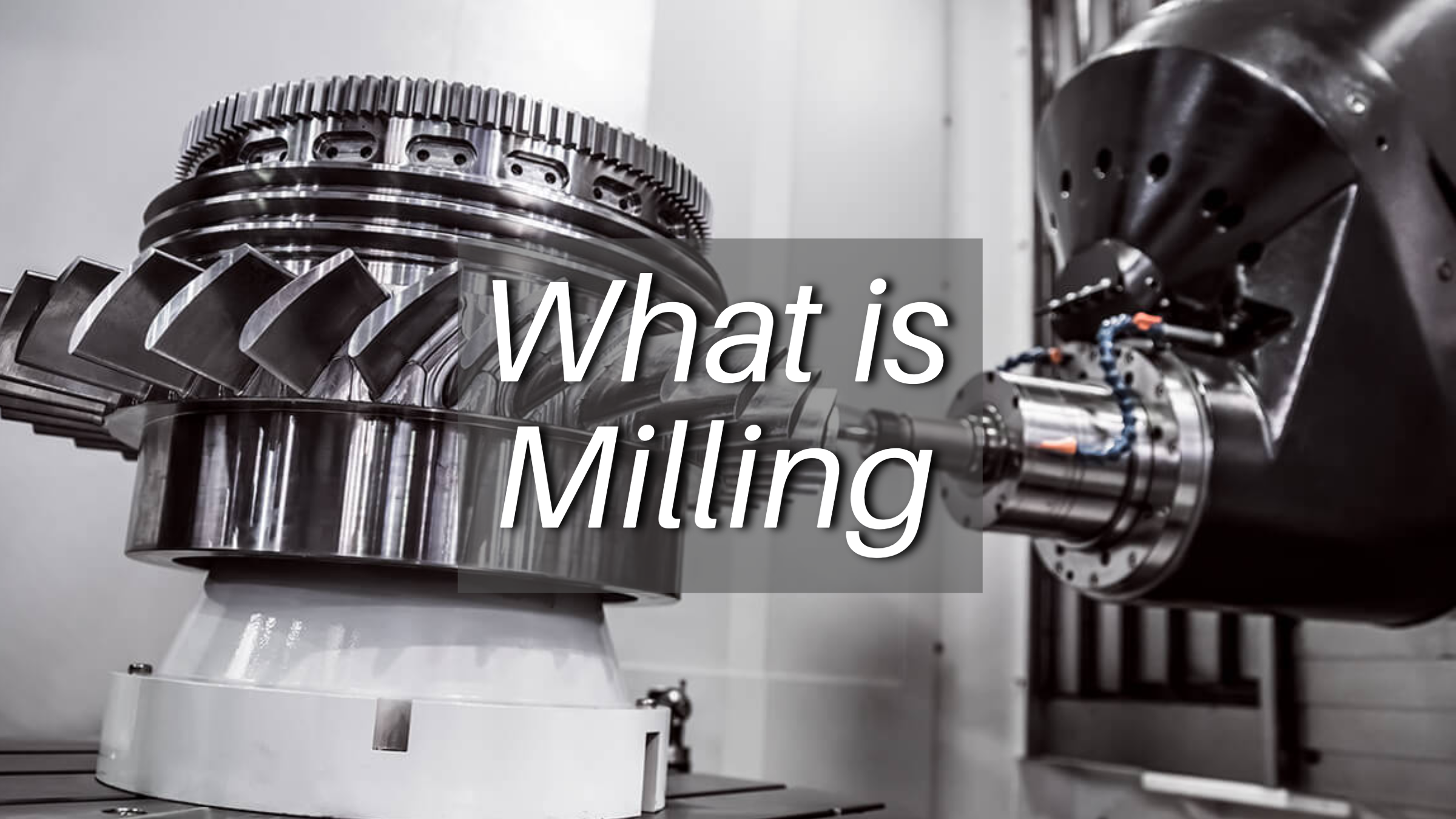
Manufacturing Insight: Define Milling Machine
Defining Milling Machines and Honyo Prototype’s Precision CNC Machining Capabilities
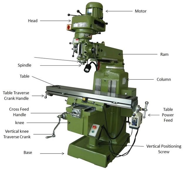
A milling machine is a foundational subtractive manufacturing tool that utilizes rotary cutting tools to systematically remove material from a workpiece, generating precise shapes, features, and geometries. Modern Computer Numerical Control (CNC) milling machines automate this process through programmed instructions, enabling exceptional accuracy, repeatability, and the ability to produce complex components from solid blocks of material. These systems are indispensable for creating critical features such as pockets, slots, contours, and threaded holes across industries including aerospace, medical, and automotive.
At Honyo Prototype, we leverage advanced CNC milling technology—including 3-axis, 4-axis, and 5-axis machining centers—to transform engineering designs into high-integrity prototypes and production parts. Our capabilities support tight tolerances down to ±0.0002 inches, multi-material processing from aluminum and stainless steel to titanium and engineering plastics, and rigorous quality control through integrated metrology. This ensures your components meet exacting functional and dimensional requirements, whether for rapid prototyping or low-volume production runs.
To accelerate your project timeline, Honyo Prototype provides an Online Instant Quote system. Simply upload your CAD file, specify materials and quantities, and receive a detailed cost estimate within hours—eliminating traditional quoting delays and enabling faster decision-making. This digital workflow streamlines your path from design to physical part without compromising on the precision or expertise inherent to our CNC machining services.
Technical Capabilities
Honyo Prototype – Technical Specifications for CNC Milling Machines
CNC milling machines at Honyo Prototype are engineered for high-precision machining across a range of advanced 3-axis, 4-axis, and 5-axis configurations. These systems support complex geometries and tight tolerance requirements essential for aerospace, medical, and industrial applications. Integrated turning capabilities on multi-axis platforms allow for complete part fabrication in a single setup, minimizing runout and improving repeatability.
The machines are optimized to process a wide range of materials including aluminum alloys (e.g., 6061, 7075), carbon and stainless steels (e.g., 4140, 17-4 PH), and engineering thermoplastics such as ABS and nylon. All systems are equipped with high-resolution feedback controls, thermal compensation, and vibration-damping structures to maintain tolerances as tight as ±0.0002″ (±0.005 mm).
Below is a summary of the core technical capabilities:
| Feature | 3-Axis Milling | 4-Axis Milling | 5-Axis Milling | Turning (Live Tooling) |
|---|---|---|---|---|
| Axis Configuration | X, Y, Z linear axes | X, Y, Z + A (rotary table) | X, Y, Z + A & B/C (tilt/rotate) | Y, Z, C (rotary spindle) |
| Max Spindle Speed | 15,000 RPM | 15,000 RPM | 18,000 RPM | 6,000 RPM |
| Positioning Accuracy | ±0.0001″ (±0.0025 mm) | ±0.0001″ (±0.0025 mm) | ±0.00008″ (±0.002 mm) | ±0.0001″ (±0.0025 mm) |
| Repeatability | ±0.00005″ (±0.0013 mm) | ±0.00005″ (±0.0013 mm) | ±0.00004″ (±0.001 mm) | ±0.00005″ (±0.0013 mm) |
| Typical Tolerance Range | ±0.0002″ – ±0.001″ | ±0.0002″ – ±0.0008″ | ±0.0002″ – ±0.0005″ | ±0.0002″ – ±0.001″ |
| Surface Finish (Ra) | 32 – 16 μin (0.8 – 0.4 μm) | 32 – 16 μin (0.8 – 0.4 μm) | 32 – 8 μin (0.8 – 0.2 μm) | 32 – 16 μin (0.8 – 0.4 μm) |
| Compatible Materials | Aluminum, Steel, ABS, Nylon | Aluminum, Steel, ABS, Nylon | Aluminum, Steel, ABS, Nylon | Aluminum, Steel |
| Max Work Envelope (X×Y×Z) | 20″ × 16″ × 12″ | 20″ × 16″ × 12″ + 360° A | 18″ × 14″ × 10″ + A/B tilt | Ø16″ × 20″ length |
| Tool Changer Capacity | 24-tool ATC | 24-tool ATC | 30-tool ATC | 12-station live tooling |
| Control System | Fanuc 31i-B5 | Fanuc 31i-B5 | Siemens 840D | Fanuc 32i |
All machines are maintained to ISO 230-2 standards for geometric accuracy and undergo monthly calibration. Honyo Prototype leverages in-process probing and laser tool measurement to ensure consistency, particularly when holding tight tolerances on critical features in aluminum, steel, ABS, and nylon components.
From CAD to Part: The Process
Honyo Prototype Milling Process: CAD to Delivery Workflow
Honyo Prototype employs a structured, technology-driven workflow to transform customer CAD models into precision-milled prototypes. This process ensures manufacturability, cost efficiency, and rapid turnaround. The term “define milling machine” refers to our methodology for selecting the optimal CNC milling strategy and machine configuration based on part geometry, material, and tolerances—not defining the machine itself. Below is the end-to-end sequence:
Upload CAD
Customers submit 3D CAD files (STEP, IGES, or native formats) via our secure portal. Our system validates file integrity, checks for missing metadata (e.g., material specifications, critical tolerances), and auto-detects geometric complexity. This step ensures all necessary data is captured before proceeding, eliminating downstream delays caused by incomplete submissions.
AI-Powered Quoting
Uploaded CAD data feeds into Honyo’s proprietary AI quoting engine, trained on 15,000+ historical milling projects. The AI analyzes part volume, feature complexity, axis requirements (3-axis vs. 5-axis), and material waste to generate a preliminary quote within 2 hours. Unlike manual quoting, our system cross-references real-time machine availability, tooling costs, and shop floor load, providing accurate lead times and cost projections. Human engineers review all AI outputs to validate feasibility.
DFM Analysis
Engineers conduct a rigorous Design for Manufacturability (DFM) review, focusing on milling-specific constraints. We identify issues such as non-optimal wall thicknesses, inadequate tool clearance, or impractical tolerances that would increase cost or scrap rates. Critical findings are summarized in a client-facing report with actionable recommendations. Common resolutions include:
| Common DFM Issue | Honyo’s Resolution | Impact on Production |
|---|---|---|
| Wall thickness < 0.8mm (aluminum) | Recommend thickening to 1.2mm or alternative support structure | Prevents chatter/vibration, reduces scrap by 35% |
| Internal radii requiring custom tooling | Suggest standard end mill radii (e.g., 0.5mm → 0.8mm) | Eliminates $200+ custom tooling cost, saves 3 days |
| Tight tolerances (±0.005mm) on non-critical surfaces | Propose relaxed tolerances (±0.025mm) per ASME Y14.5 | Lowers machining time by 22%, maintains function |
Production
Approved designs move to production on our certified Haas and DMG MORI milling centers. Each job undergoes:
Machine Allocation: Parts are assigned to optimal machines (e.g., 5-axis for complex contours, high-speed spindles for aluminum).
In-Process Inspection: On-machine probing verifies critical dimensions after roughing and before finishing.
Material Traceability: Batch numbers and heat-treated certs logged for aerospace/medical clients.
All processes adhere to ISO 9001:2015 standards, with first-article inspection reports provided upon request.
Delivery
Completed parts undergo final QA using CMMs or optical comparators against the original CAD model. We package components with anti-corrosion VCI paper and custom foam inserts for fragile geometries. Delivery includes:
Dimensional inspection report (per AS9102 for aerospace)
Material certification
Digital as-built model (if post-machining scans were performed)
Standard lead time is 5–7 business days for 3-axis milling; expedited 72-hour service available for qualified projects.
This integrated workflow reduces prototyping lead times by 40% compared to industry averages while ensuring first-pass yield rates exceed 92%. By anchoring decisions in DFM-driven machine selection and AI-optimized scheduling, Honyo eliminates guesswork in milling process definition.
Start Your Project
Learn more about our precision milling capabilities at Honyo Prototype. For detailed specifications on our CNC milling machines and manufacturing services, contact Susan Leo at [email protected]. Our advanced production facility is located in Shenzhen, China, ensuring high-quality prototyping and low-volume manufacturing with fast turnaround times.
🚀 Rapid Prototyping Estimator
Estimate rough cost index based on volume.