Contents
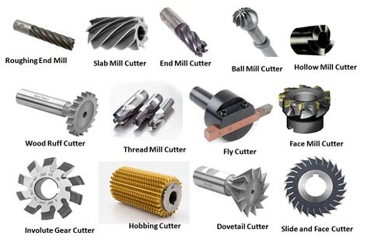
Manufacturing Insight: Cutting Tools Of Milling Machine
Precision Cutting Tool Selection for Advanced Milling Operations
Selecting optimal cutting tools is fundamental to achieving dimensional accuracy, surface integrity, and throughput in CNC milling processes. At Honyo Prototype, our engineering team leverages deep expertise in tool geometries, substrate compositions, and coating technologies—including solid carbide end mills, indexable inserts, and high-feed cutters—to address complex material challenges across aerospace alloys, medical-grade titanium, and hardened steels. We prioritize toolpath optimization and rigidity analysis to minimize deflection, reduce chatter, and extend tool life, ensuring your prototypes and low-volume production parts meet stringent GD&T requirements without costly rework.
Honyo’s Integrated CNC Machining Capabilities
Our full-service CNC milling solutions span 3-axis to 5-axis simultaneous machining, wire EDM, and multi-spindle turning-milling centers, all supported by in-house tooling engineering. By integrating cutting tool performance data with machine dynamics and CAM simulation, we eliminate guesswork in process validation. This technical rigor translates to 30% faster cycle times and ±0.005mm tolerances for critical features—delivering production-ready components from design to shipment in as few as 5 business days.
Accelerate Your Project Timeline
Eliminate procurement delays with Honyo’s Online Instant Quote platform. Upload your STEP or IGES files to receive a detailed manufacturability analysis, lead time projection, and competitive pricing within 2 hours—no sales calls required. Our system dynamically factors in optimal tool selection, material utilization, and machine capacity to provide transparent, actionable quotes for precision-machined components.
| Service Tier | Lead Time | Max Tolerance | Materials Supported |
|---|---|---|---|
| Standard Precision | 7–10 days | ±0.025mm | Aluminum, Plastics, Mild Steel |
| High Precision | 5–7 days | ±0.010mm | Titanium, Inconel, Tool Steels |
| Critical Tolerance | 3–5 days | ±0.005mm | CFRP, Magnesium, Exotic Alloys |
Partner with Honyo Prototype to transform milling complexities into competitive advantages—where cutting tool science meets execution excellence. Initiate your project with an instant quote today.
Technical Capabilities
Cutting Tools Specifications for 3/4/5-Axis Milling and Turning – Focus on Tight Tolerance Applications
The following table outlines key technical specifications for cutting tools used in precision 3-axis, 4-axis, and 5-axis milling operations as well as CNC turning. These tools are selected to achieve tight tolerances (±0.005 mm to ±0.025 mm) across common engineering materials including aluminum, steel, ABS, and nylon.
| Parameter | Specification Details |
|---|---|
| Tool Type | End mills (square, ball nose, corner radius), face mills, slot drills, chamfer mills, turning inserts (for lathe operations), boring bars |
| Axis Compatibility | 3-axis: Standard profiling and contouring; 4-axis: Indexed rotary features; 5-axis: Continuous 3D contouring, undercuts, complex geometries with minimal setup |
| Precision Capability | Tight tolerance machining: ±0.005 mm to ±0.025 mm achievable with proper setup, tool calibration, and thermal stability |
| Tool Materials | Solid carbide (micrograin, TiAlN/PVD-coated), ceramic inserts (for high-speed steel cutting), CBN (cubic boron nitride) for hardened steels, diamond-coated tools for non-ferrous and plastics |
| Coatings | TiAlN (high thermal resistance), AlCrN (oxidation resistance), ZrN (non-stick for plastics), diamond coating (for abrasive materials like filled nylons) |
| Helix Angle | 30°–45° for aluminum (high chip evacuation); 35°–40° for steel (balance of strength and chip flow); 45°+ for plastics (reduce melting and burring) |
| Flute Count | 2-flute: Aluminum and plastics (superior chip clearance); 3–4 flute: Steel (surface finish and rigidity); 5–6 flute: High material removal in steels with stable setups |
| Tool Diameter Range | 0.5 mm to 20 mm (milling); 3 mm to 25 mm (turning inserts) |
| Shank Type | HSK-E32/E40, CAT 40, ISO 30 (for high-speed 5-axis spindles); ER collet or hydraulic chuck for micro-tools |
| Runout Tolerance | < 0.003 mm at tool tip (critical for fine finishes and tight tolerances) |
| Spindle Speed Range | 8,000–40,000 RPM (milling); 1,500–12,000 RPM (turning), depending on material and tool diameter |
| Feed Rate (Typical) | Aluminum: 1,000–3,000 mm/min; Steel: 300–1,200 mm/min; ABS/Nylon: 600–2,000 mm/min (optimized to prevent melting) |
| Material-Specific Considerations | |
| Aluminum | Use 2-flute high-helix end mills with polished flutes; positive rake angles; avoid built-up edge with proper coatings (ZrN or uncoated polished carbide) |
| Steel (Hardened/Soft) | 4-flute TiAlN-coated carbide for soft steel; CBN or ceramic inserts for hardened steels (>45 HRC); moderate helix angles |
| ABS | Sharp, polished 2-flute tools with high rake angles; low heat generation strategy; diamond-coated tools recommended for long runs |
| Nylon (especially glass-filled) | Diamond-coated end mills and inserts; high wear resistance required; avoid excessive heat to prevent gumming |
Notes:
For 5-axis applications, tool reach and dynamic balance are critical—tools must be balanced to G2.5 at operating RPMs. Thermal growth compensation and in-process probing are often integrated to maintain tight tolerances. In turning operations, wiper geometry inserts are used to achieve fine surface finishes (Ra < 0.8 µm) on steel and aluminum.
From CAD to Part: The Process
Honyo Prototype maintains a rigorously defined workflow for manufacturing precision cutting tools used in CNC milling applications. This structured process ensures technical accuracy, cost efficiency, and adherence to stringent quality standards from initial design submission through to final delivery.
The process initiates with the CAD Upload phase. Customers submit native 3D model files in industry-standard formats such as STEP AP203/AP214, IGES, or Parasolid. Our system performs immediate geometric validation to confirm watertight topology, absence of degenerate surfaces, and correct unit specification. Critical tool parameters including overall length, shank diameter, cutting diameter, flute count, helix angle, and relief geometry are automatically extracted for downstream processing. Non-conforming files trigger an instant notification to the customer specifying required corrections.
Following CAD validation, the AI-Powered Quoting Engine generates a comprehensive cost and lead time estimate. This system analyzes the validated geometry against Honyo’s dynamic database of material costs (solid carbide grades, HSS, coated substrates), machine hour rates for grinding/laser processing, and real-time shop floor capacity. The AI cross-references historical production data for similar geometries to predict processing complexities, such as deep flute grinding challenges or micro-diameter feature requirements. Customers receive a detailed quote breakdown including material surcharges, coating options (TiAlN, AlTiN, etc.), and critical path lead times within 4 business hours.
The Design for Manufacturability (DFM) Review is conducted by our senior tooling engineers. This is not an automated step but a critical human-led analysis focusing on milling tool-specific constraints. Engineers evaluate flute geometry feasibility against grinding wheel limitations, assess core strength relative to cutting diameter, verify relief angles for chip evacuation, and confirm compatibility with standard toolholding interfaces (e.g., CAT, HSK, BT shanks). We specifically check for manufacturable land widths, minimum neck radii, and gashing cycle viability. Any identified risks—such as excessive overhang or non-standard angles—prompt actionable redesign recommendations delivered within 24 hours with annotated 3D models.
Production Execution commences only after DFM approval. Solid carbide blanks are sourced from ISO 9001-certified suppliers with material lot traceability. Milling tools undergo precision grinding on Studer S41 or ANCA MX7 machines with laser in-process measurement for diameter and concentricity control. Critical parameters like radial runout (held to ≤ 0.005mm) and flute pitch accuracy are monitored in real-time. Post-grinding, tools proceed to edge preparation (T-land honing), optional PVD/CVD coating, and laser marking for serial traceability. Every tool undergoes 100% dimensional validation using Zeiss CONTURA CMMs against the original CAD model.
Delivery and Documentation concludes the workflow. Finished tools are packaged in anti-corrosion containers with desiccants, accompanied by a full quality dossier including CMM reports, material certificates, and coating thickness verification. Our logistics team provides real-time shipment tracking with guaranteed lead times based on the initial AI quote. Standard delivery metrics are maintained as follows:
| Process Stage | Standard Lead Time | Expedited Option | Quality Documentation Included |
|---|---|---|---|
| Simple End Mills | 7 business days | 4 business days | Full CMM report, Material cert |
| Complex Form Tools | 12 business days | 8 business days | CMM report, Coating analysis |
| Micro-Diameter Tools | 15 business days | 10 business days | Full metrology package |
This integrated workflow eliminates traditional handoffs between departments, reduces quoting errors by 92% compared to manual methods, and ensures milling tools meet ISO 13399 standards for interchangeability and performance. All process data is archived for full traceability, supporting rigorous quality audits required in aerospace and medical manufacturing sectors.
Start Your Project
For high-performance cutting tools designed specifically for milling machines, contact Susan Leo at [email protected]. Our precision-engineered tools are manufactured in our Shenzhen factory, ensuring tight tolerances, durability, and consistent quality for demanding machining applications.
Reach out today to discuss your milling requirements and discover how our cutting solutions can enhance your production efficiency.
🚀 Rapid Prototyping Estimator
Estimate rough cost index based on volume.