Contents
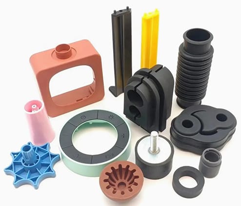
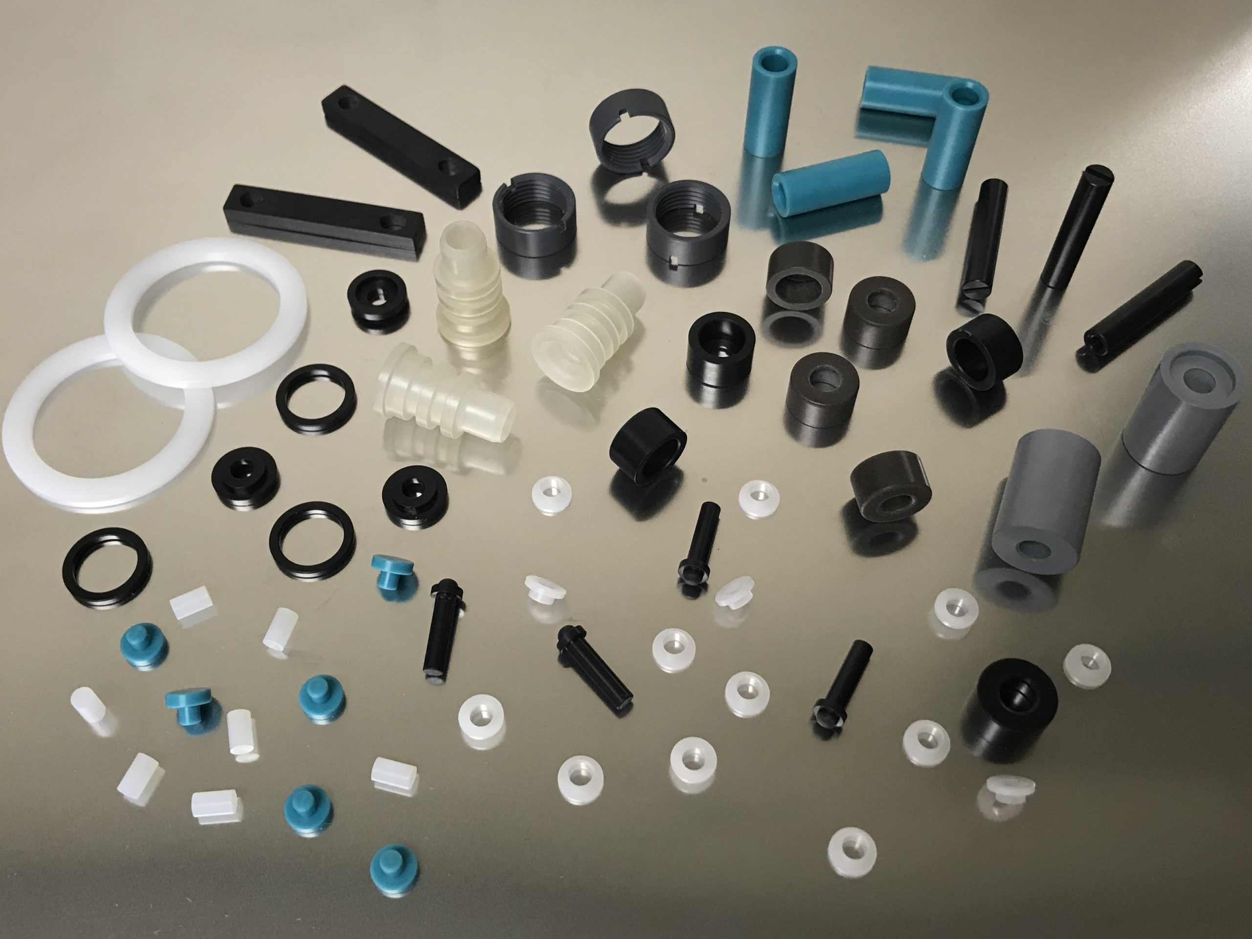
Manufacturing Insight: Custom Plastic Pieces
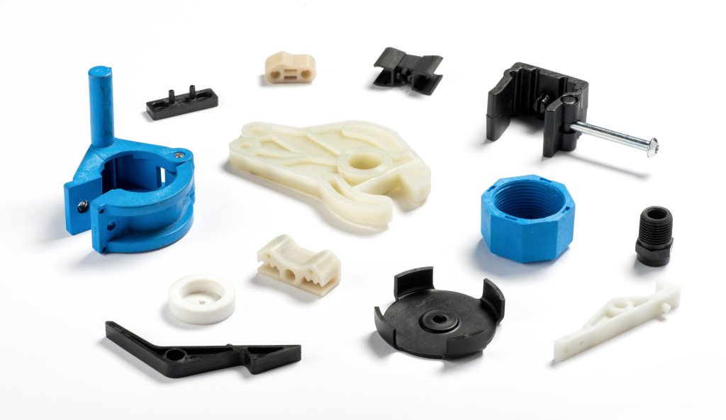
Precision Custom Plastic Components via Advanced CNC Machining
Honyo Prototype delivers mission-critical custom plastic pieces engineered for performance in demanding industrial, medical, and aerospace applications. Our CNC machining capabilities transform engineering-grade thermoplastics—including Delrin, Ultem, PEEK, and acrylic—into complex geometries with tolerances held to ±0.0002 inches. Unlike additive methods, CNC machining eliminates layer lines and internal stresses, ensuring structural integrity for load-bearing components, fluidic systems, and high-precision housings.
We specialize in rapid prototyping and low-volume production of plastics requiring exact material properties: chemical resistance, thermal stability, or optical clarity. Our HAAS and DMG MORI 5-axis centers, coupled with in-house material certification and first-article inspection (FAI) per AS9102, guarantee repeatability from prototype to pilot run. This process is ideal for parts where injection molding tooling costs are prohibitive or design iterations are frequent.
Accelerate your development timeline with Honyo’s Online Instant Quote platform. Upload your STEP or IGES file, specify material and quantity, and receive a detailed manufacturing assessment—including lead time and DFM feedback—within minutes. No sales calls or email delays: validate feasibility and cost at the speed of design iteration.
For engineers requiring certified, high-fidelity plastic components without compromising on speed or precision, Honyo Prototype bridges the gap between concept and functional reality.
Technical Capabilities
Custom plastic and metal components produced via 3/4/5-axis milling and turning require precise technical specifications to meet tight tolerance requirements in demanding applications. These processes enable complex geometries, high repeatability, and superior surface finishes. Below is a summary of key technical specifications by material type and manufacturing method.
Technical Specifications for Custom Plastic and Metal Components
| Parameter | 3-Axis Milling | 4-Axis Milling | 5-Axis Milling | CNC Turning | Typical Tolerance (Machined) | Surface Finish (Ra) |
|---|---|---|---|---|---|---|
| Aluminum (e.g., 6061, 7075) | Max work envelope: 1000 x 600 x 500 mm | Rotary axis (A): ±360° indexing | Full continuous motion on B and C axes | Diameter range: 2 – 150 mm | ±0.005 mm (±0.0002″) | 0.8 – 3.2 µm |
| Steel (e.g., 4140, 17-4 PH) | Max work envelope: 800 x 500 x 400 mm | Fourth axis allows undercut features | Simultaneous 5-axis for complex contours | Max length: 300 mm | ±0.010 mm (±0.0004″) | 0.8 – 1.6 µm |
| ABS (Acrylonitrile Butadiene Styrene) | Max size: 600 x 400 x 300 mm | Limited to non-continuous 4-axis | Best for prototypes and enclosures | OD/ID turning possible | ±0.05 mm (±0.002″) | 3.2 – 6.3 µm |
| Nylon (Polyamide, e.g., PA6, PA66) | Max size: 500 x 400 x 250 mm | Indexing only; avoid high heat | Low thermal conductivity; requires cooling | Threaded features, bushings | ±0.05 mm (±0.002″) | 3.2 – 6.3 µm |
Notes on Capabilities and Materials
3-axis milling is ideal for prismatic parts with flat or orthogonal features. It supports high-speed machining of both metals and engineering plastics with tight tolerances, especially in aluminum and steel.
4-axis milling adds rotational capability (typically A-axis), enabling machining of features on multiple faces without manual repositioning. This is beneficial for parts requiring ports, cutouts, or contours around a central axis.
5-axis machining (full simultaneous or 3+2 positioning) delivers the highest complexity handling, particularly for organic shapes, deep cavities, and compound angles. It minimizes setup changes and improves accuracy, especially critical in aerospace or medical metal components.
CNC turning is used for cylindrical components such as shafts, fittings, and threaded parts. When combined with milling (mill-turn centers), it supports hybrid geometries in both metals and plastics.
Aluminum and steel are machined to tight tolerances (down to ±0.005 mm) with excellent surface finishes due to their favorable cutting characteristics. ABS and nylon, while less dimensionally stable than metals, can still achieve ±0.05 mm tolerances with proper fixturing and thermal management. These plastics require lower cutting speeds and sharp tooling to prevent melting or burring.
All parts are inspected using CMM, optical comparators, or laser scanning to verify conformance to GD&T specifications. First Article Inspection (FAI) reports are available upon request.
From CAD to Part: The Process
Honyo Prototype Custom Plastic Piece Manufacturing Process
Honyo Prototype executes custom plastic component production through a rigorously defined, technology-integrated workflow designed for speed, precision, and risk mitigation. This process ensures alignment between client design intent and manufacturable outcomes while maintaining transparency at every stage.
CAD Upload and Initial Processing
Clients initiate the process by uploading native or neutral CAD files (STEP, IGES, Parasolid, or native formats like SLDPRT, IPT, PRT) via our secure customer portal. Our system performs immediate validation checks for file integrity, unit consistency, and geometric completeness. Proprietary encryption protocols protect all intellectual property throughout transmission and storage. Unsupported formats or incomplete geometry trigger automated notifications requesting clarification, minimizing downstream delays.
AI-Powered Quoting Engine
Uploaded designs enter our AI-driven quoting system, which cross-references over 10 million historical production records and real-time material/machine data. The algorithm evaluates part geometry, material specifications, tolerance requirements, and volume to generate a preliminary cost and timeline estimate within 24 hours. This phase incorporates dynamic factors including resin market volatility, machine availability, and secondary operation complexity. Crucially, the AI output undergoes mandatory validation by a senior process engineer to ensure contextual accuracy—preventing over- or under-quoting scenarios common with fully automated systems.
Engineering-Led DFM Analysis
Following quote acceptance, our manufacturing engineering team conducts a comprehensive Design for Manufacturability (DFM) review. This is not a checklist but a collaborative engineering dialogue focused on eliminating production risks. Key assessment parameters include:
| DFM Parameter | Critical Thresholds | Typical Resolution Path |
|---|---|---|
| Wall Thickness Uniformity | Minimum 0.6mm; Max differential ≤25% of nominal | Rib redesign, core shifting |
| Draft Angles | ≥1° per side for textured surfaces | Feature remapping, split-line adjustment |
| Undercut Complexity | Zero manual pick-outs for high-volume orders | Slider/cam integration planning |
| Gate Location Feasibility | Avoidance of critical cosmetic surfaces | Mold flow simulation validation |
Engineers provide annotated CAD markups and tolerance stack-up analyses within 48 hours, offering specific design modifications to optimize cost, cycle time, and part functionality. Client approval of DFM recommendations is required prior to tooling commencement.
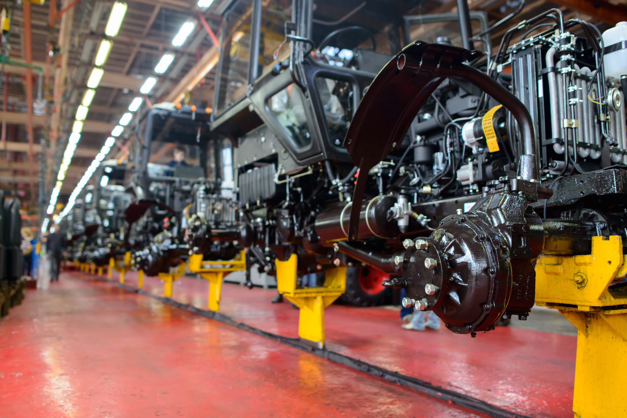
Precision Production Execution
Approved designs advance to production using technology matched to volume and complexity requirements. Low-volume prototypes (1–100 pcs) utilize industrial-grade injection molding with aluminum tooling or high-resolution additive processes (MJF, SLS). Mid-to-high volumes (100+ pcs) employ hardened steel molds on automated presses with in-mold sensing. All processes adhere to ISO 9001-controlled workflows featuring:
Real-time cavity pressure monitoring for dimensional stability
First-article inspection per AS9102 standards with full CMM reporting
Batch traceability via serialized part marking and material lot tracking
Environmental controls maintaining ±2°C temperature stability in molding cells
Quality-Controlled Delivery
Final parts undergo rigorous validation against the approved DFM package. Dimensional reports, material certificates (including RoHS/REACH compliance documentation), and process capability data (Cp/Cpk) ship with the order. Parts are packaged using ESD-safe materials with humidity indicators for sensitive polymers. Delivery includes real-time logistics tracking and a post-delivery engineering debrief to document lessons learned. Standard lead times range from 10 days for 3D-printed prototypes to 25 days for production-grade injection molding, with expedited options available.
This integrated approach reduces time-to-part by 30–50% compared to traditional prototyping vendors while virtually eliminating costly design rework through upfront engineering collaboration. Honyo’s closed-loop system ensures every custom plastic component meets both functional specifications and production scalability requirements.
Start Your Project
Looking for custom plastic pieces tailored to your specifications? Partner with Honyo Prototype for precision-manufactured components produced at our Shenzhen factory. With advanced in-house capabilities and strict quality control, we deliver high-quality plastic parts fast—ideal for prototypes and low-volume production.
Contact Susan Leo today at [email protected] to discuss your project requirements and receive a competitive quote.
🚀 Rapid Prototyping Estimator
Estimate rough cost index based on volume.