Contents
Manufacturing Insight: Custom Bent Sheet Metal
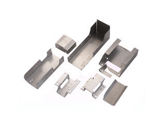
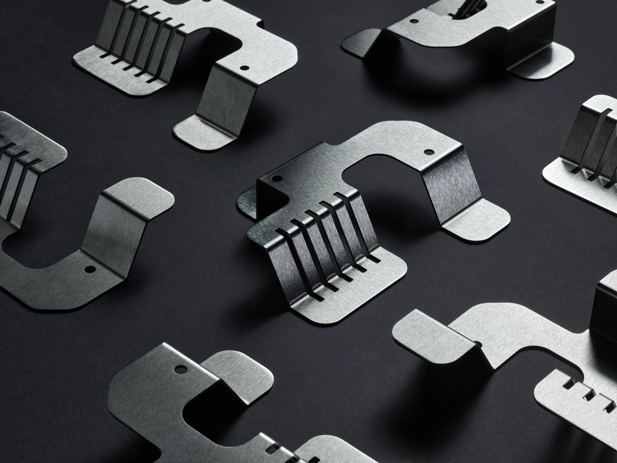
Precision Custom Bent Sheet Metal Fabrication for Demanding Applications
At Honyo Prototype, we engineer custom bent sheet metal solutions where precision, repeatability, and material integrity are non-negotiable. Our advanced CNC press brake fleet, paired with certified tooling and operator expertise, consistently achieves complex geometries, tight tolerances down to ±0.005 inches, and clean bends across materials including aluminum alloys, stainless steel, and mild steel up to 0.25-inch thickness. We specialize in low-to-mid volume production runs where design complexity often challenges conventional fabricators, ensuring your enclosures, brackets, and structural components meet exact functional and aesthetic requirements without costly rework.
Streamlined Quoting Accelerates Your Project Timeline
Leverage our Online Instant Quote platform to receive detailed, accurate pricing for custom bent sheet metal parts in under 60 seconds. Upload your STEP or DXF file, specify material, finish, and quantity, and our system dynamically calculates manufacturability feedback alongside cost—eliminating days of email delays. This integration of engineering validation and real-time costing empowers design teams to iterate confidently and procurement specialists to forecast budgets with certainty.
Honyo Prototype delivers more than formed metal; we provide a frictionless path from concept to certified production-ready components, backed by rigorous in-process inspection and AS9100-aligned quality controls. For engineering teams prioritizing speed without compromise, our bent sheet metal capabilities form the foundation of reliable, high-performance assemblies.
Technical Capabilities
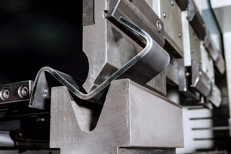
Custom bent sheet metal fabrication involves precision processes including laser cutting, bending, and welding to produce components to exact design specifications. These operations are performed on a range of materials including aluminum, steel, and select thermoplastics such as ABS and nylon, though with important distinctions in process compatibility.
Laser cutting provides high-accuracy profiling of flat sheet stock using focused CO₂ or fiber lasers. Bending is typically accomplished via CNC press braking to achieve precise angular formations. Welding joins components using methods such as MIG, TIG, or spot welding, depending on material and joint requirements. Thermoplastics like ABS and nylon are generally not welded using metal techniques and require alternative joining methods such as solvent bonding or ultrasonic welding.
Below is a summary of technical specifications and process compatibility for each material:
| Material | Thickness Range (mm) | Laser Cutting Compatibility | Bending Compatibility | Welding Compatibility | Notes |
|---|---|---|---|---|---|
| Aluminum | 0.5 – 12.7 | Excellent (fiber laser recommended) | Excellent (springback ~2°) | Excellent (TIG/MIG preferred) | Anodizing may affect weld strength; clean edges pre-weld |
| Mild Steel | 0.8 – 25.4 | Excellent (CO₂ or fiber laser) | Excellent (minimal springback) | Excellent (MIG/TIG/Spot) | Prone to rust; consider powder coating or plating |
| Stainless Steel | 0.8 – 19.0 | Excellent (fiber laser) | Good (higher springback) | Excellent (TIG for precision) | Higher cost; superior corrosion resistance |
| ABS | 1.0 – 10.0 | Good (CO₂ laser with ventilation) | Limited (requires heated bending) | Not compatible with metal welding | Use solvent cement or mechanical fasteners |
| Nylon | 1.0 – 10.0 | Fair (CO₂ laser, high risk of melting) | Poor (high elasticity, creep) | Not compatible with metal welding | Best joined via mechanical fastening or ultrasonic welding |
Note: While ABS and nylon are not traditional sheet metals, they are sometimes included in custom bent fabrication for hybrid assemblies. However, they require specialized handling and cannot undergo standard metal welding or cold bending processes.
From CAD to Part: The Process
Honyo Prototype executes custom bent sheet metal fabrication through a rigorously controlled digital workflow designed for precision, efficiency, and seamless client collaboration. Our process begins when a client uploads their native CAD file (STEP, IGES, SolidWorks, DXF, or DWG) directly to our secure online portal. The system automatically validates critical inputs including material type, thickness, geometric complexity, and required tolerances, ensuring the design aligns with fundamental manufacturing capabilities before proceeding.
The validated CAD data feeds into our proprietary AI-powered quoting engine. This system analyzes the 3D model to generate an accurate, detailed cost estimate within hours, not days. Unlike basic area-based quoting, our AI evaluates bend count, tooling requirements, secondary operations (such as tapping, welding, or finishing), material yield optimization, and machine time based on actual geometric complexity. The quote includes clear breakdowns of costs per operation and lead time projections, providing immediate transparency.
Following quote acceptance, the project enters our mandatory Design for Manufacturability (DFM) review. This is not an automated step; our senior manufacturing engineers conduct a thorough manual analysis. We examine bend radii against material properties, assess minimum flange lengths, verify hole-to-bend clearance, evaluate grain direction for visible surfaces, and identify potential deformation risks in complex geometries. Crucially, we provide actionable feedback and optimization suggestions directly within the client’s CAD environment via our collaborative platform. This collaborative iteration ensures the design achieves target functionality while maximizing manufacturability and minimizing cost – a step many competitors omit, leading to production delays and cost overruns.
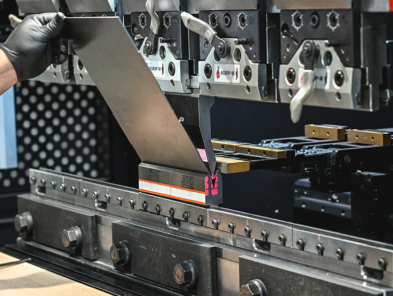
Once DFM is approved, the job moves to production. Our CNC press brakes (ranging from 50 to 300 tons) are programmed using the finalized CAD data, ensuring precise backgauging and bend sequencing. We utilize 3D laser verification systems for first-article inspection on critical dimensions, confirming alignment with the original model and specified tolerances. Below are the standard bend tolerances we achieve across common materials:
| Dimension Type | Tolerance (Per ISO 2768-mK) | Applicable Material Thickness Range |
|---|---|---|
| Bend Angle | ±0.5° | 0.5mm – 3.0mm |
| Bend Radius | ±0.2mm | All thicknesses |
| Linear Dimension (Flange) | ±0.2mm | 0.5mm – 3.0mm |
| Hole to Bend Edge | ±0.3mm | All thicknesses |
All parts undergo in-process inspection at critical stages, with full traceability via barcode tracking from raw material to shipment. Secondary operations are sequenced to minimize handling, and surface finishes are applied only after forming to prevent marring.
Final inspection verifies all dimensions against the approved drawing, including first-article reporting for client sign-off if required. Parts are meticulously packaged using anti-corrosion materials and custom fixtures to prevent transit damage, then shipped via the client’s preferred carrier with real-time tracking. Dedicated project managers provide proactive updates throughout the entire cycle, ensuring on-time delivery typically within 5-10 business days for standard complexity jobs. This integrated process, combining AI efficiency with deep engineering expertise, guarantees that every custom bent sheet metal component meets Honyo’s stringent quality standards while optimizing time-to-market for our clients.
Start Your Project
Looking for precision custom bent sheet metal components? Partner with Honyo Prototype for high-quality fabrication from our Shenzhen manufacturing facility.
Contact Susan Leo today at [email protected] to discuss your project requirements and receive a competitive quote.
🚀 Rapid Prototyping Estimator
Estimate rough cost index based on volume.