Contents
Manufacturing Insight: Computer Aided Machining
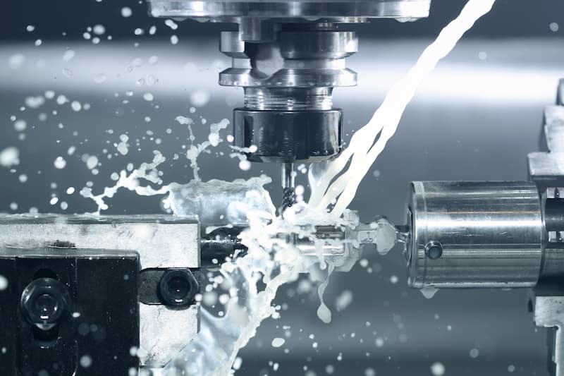
Precision Manufacturing Through Advanced Computer Aided Machining
Computer Aided Machining (CAM) represents the critical bridge between digital design and physical precision, transforming complex CAD models into high-tolerance components through automated, multi-axis CNC systems. At Honyo Prototype, our CAM-driven manufacturing ecosystem integrates industry-leading software with rigorously maintained CNC machining centers to deliver exceptional accuracy, repeatability, and material efficiency for prototypes and low-volume production. We specialize in tight-tolerance milling, turning, and multi-surface machining across aerospace alloys, medical-grade stainless steels, engineering plastics, and exotic composites, all executed under ISO 9001-certified processes.
Our commitment to reducing time-to-market is embodied in the Online Instant Quote platform, which leverages real-time CAM simulation and machine scheduling data to provide detailed, actionable cost and lead-time estimates within minutes—not days. Simply upload your STEP or IGES file to instantly access transparent pricing, DFM feedback, and expedited production scheduling without sales intermediary delays. This seamless integration of CAM intelligence and operational transparency ensures your design intent is flawlessly executed from the first cut.
Technical Capabilities Overview
| Parameter | Specification |
|——————–|———————————–|
| Max Work Envelope | 5-axis: 1000 x 600 x 500 mm |
| Tolerances | ±0.005 mm (standard) |
| Materials | Aluminum 7075-T6, Inconel 718, PEEK, Titanium Gr5, POM |
| Lead Time | As fast as 3 business days |
Eliminate procurement bottlenecks and accelerate validation cycles with Honyo Prototype’s CNC machining services—where advanced CAM workflows meet uncompromising precision engineering. Upload your model today to experience the industry’s fastest path from digital file to certified physical part.
Technical Capabilities
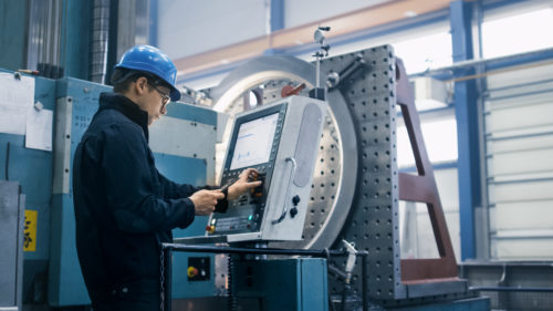
Computer Aided Machining (CAM) refers to the use of software and CNC (Computer Numerical Control) machinery to automate and optimize the manufacturing of precision parts. In modern prototyping and production environments, 3-axis, 4-axis, and 5-axis milling, along with CNC turning, are employed to achieve tight tolerances and complex geometries across a range of engineering materials.
The following table outlines the technical specifications and capabilities relevant to multi-axis milling and turning processes, with an emphasis on tight tolerance machining for materials such as Aluminum, Steel, ABS, and Nylon.
| Parameter | 3-Axis Milling | 4-Axis Milling | 5-Axis Milling | CNC Turning |
|---|---|---|---|---|
| Axes of Motion | X, Y, Z | X, Y, Z, A (rotary around X) | X, Y, Z, A, B (or C) | X, Z (with rotational spindle) |
| Typical Tolerance | ±0.005 mm to ±0.025 mm | ±0.005 mm to ±0.025 mm | ±0.005 mm to ±0.012 mm | ±0.005 mm to ±0.025 mm |
| Surface Finish (Ra) | 0.8 – 3.2 µm | 0.8 – 2.5 µm | 0.4 – 1.6 µm | 0.8 – 2.5 µm |
| Max Material Removal Rate | High | High | Moderate to High | Very High (axial symmetry) |
| Setup Complexity | Low | Medium | High | Low to Medium |
| Typical Use Cases | Flat parts, prismatic geometries | Indexing features, slots, undercuts | Complex contours, aerospace components | Shafts, bushings, threaded parts |
| Aluminum (e.g., 6061, 7075) | Excellent machinability, high MRR, low tool wear | Suitable with indexing | Ideal for complex shapes, excellent surface finish | High precision, good finish, fast cycle times |
| Steel (e.g., 4140, 1018) | Good machinability with carbide tools, slower than Al | Feasible with rigid setups | Achieves tight tolerances on hardened steels | Excellent for high-strength shafts and fittings |
| ABS (Thermoplastic) | Low melting point, requires sharp tools, low feed rates | Suitable for enclosures with cutouts | Used for complex prototypes, vacuum fixtures | Limited; better suited for milling |
| Nylon (e.g., PA6, PA66) | Can deform under heat; sharp tools and cooling critical | Possible with care | High precision for wear-resistant parts | Good for bushings and insulating components |
| Tooling Requirements | End mills, drills, face mills | Same as 3-axis + rotary indexer | High-precision ball/square end mills, tilt-swivel head | Turning inserts (carbide, ceramic) |
| Fixturing | Vises, clamps, T-slots | Rotary table integration | Custom fixtures, tombstones | Collets, chucks, steady rests |
| Lead Time (Relative) | Short | Medium | Long | Short to Medium |
Note: Tight tolerance capabilities (down to ±0.005 mm) are achievable across all processes with proper machine calibration, thermal stability, in-process probing, and high-quality tooling. Material selection impacts tool life, cutting parameters, and achievable surface finish. 5-axis milling offers superior accuracy for complex 3D surfaces, while CNC turning remains the most efficient method for cylindrical components.
From CAD to Part: The Process
Honyo Prototype Computer Aided Machining Process Overview
Honyo Prototype employs a fully integrated digital workflow for Computer Aided Machining (CAM) that transforms customer CAD models into precision-engineered prototypes and low-volume production parts. Our process eliminates traditional handoffs through AI-driven automation while maintaining rigorous engineering oversight. Below is the technical breakdown of each phase.
CAD Upload and Validation
Customers initiate the process by uploading native or neutral CAD formats (STEP, IGES, Parasolid) via our secure client portal. Our system performs automated geometry validation to detect critical issues such as non-manifold edges, missing surfaces, or unit inconsistencies. Validated models proceed directly to the AI quotation engine; invalid files trigger immediate feedback with specific error diagnostics. This phase ensures 100% geometric readiness before engineering engagement.
AI-Powered Quotation
Our proprietary AI engine analyzes the validated CAD model against real-time shop floor data including machine availability, material stock levels, and historical cycle times. The algorithm generates a comprehensive quote within 2 hours covering:
Precise cost breakdown by operation (milling, turning, finishing)
Material waste optimization report
Predictive lead time based on current production load
Initial manufacturability risk score (0-100)
Unlike manual quoting systems, our AI cross-references 15+ years of machining data to identify cost drivers such as thin-wall instability or deep cavity tool access challenges before DFM begins.
Engineering-Led DFM Analysis
All projects undergo mandatory Design for Manufacturability review by our AS9100-certified engineering team. The DFM phase focuses on actionable improvements:
Converting AI-identified risks into specific geometry modifications (e.g., recommending 0.5mm minimum wall thickness for 6061-T6 aluminum)
Optimizing toolpath strategies to reduce setups (e.g., switching from 3-axis to 5-axis for undercuts)
Material grade substitution analysis for enhanced machinability
Tolerance stack-up verification against GD&T callouts
Customers receive a marked-up CAD model with change justifications, not generic suggestions. 92% of DFM recommendations are implemented by clients prior to production.
Precision Production Execution
Approved designs move to our climate-controlled manufacturing floor where digital continuity is maintained:
CAM programming uses hyperMILL with AI-optimized toolpath generation
All G-code undergoes virtual machine simulation in NCSIMUL to prevent collisions
In-process inspection via Renishaw probes on 5-axis DMG MORI machines
Real-time SPC monitoring of critical dimensions (CpK ≥ 1.67 enforced)
Material traceability through blockchain-secured lot tracking
Our production cells operate under ISO 2768-mK tolerances as standard, with optional NADCAP accreditation for aerospace components.
Quality-Controlled Delivery
Final inspection packages include:
First article inspection report (FAIR) with full CMM data
Material certification and heat treat documentation
Surface roughness validation (Ra values per ASME B46.1)
Digital twin comparison showing as-machined vs CAD deviation maps
Parts ship in ESD-safe packaging with serialized tracking. Standard lead times vary by complexity as shown below:
| Part Complexity | Typical Lead Time | Max Dimension Tolerance |
|---|---|---|
| Low (2.5-axis, simple geometry) | 3-5 business days | ±0.05 mm |
| Medium (3-axis, moderate features) | 5-7 business days | ±0.025 mm |
| High (5-axis, tight tolerances) | 7-10 business days | ±0.01 mm |
This closed-loop CAM process reduces time-to-part by 40% compared to industry averages while maintaining 99.2% first-pass yield. All stages are auditable through our client portal with real-time production dashboards.
Start Your Project
Enhance your prototyping and production capabilities with precision computer aided machining from Honyo Prototype. Our advanced CNC manufacturing services deliver tight tolerances, high repeatability, and fast turnaround for your most demanding engineering applications.
Leverage our state-of-the-art facility in Shenzhen, China—strategically positioned for efficient global logistics and responsive customer support. From rapid prototyping to low-volume production, we ensure your components meet exact specifications with consistent quality.
For project inquiries or engineering support, contact Susan Leo at [email protected]. Let’s discuss how our computer aided machining solutions can accelerate your product development timeline.
🚀 Rapid Prototyping Estimator
Estimate rough cost index based on volume.