Contents
Manufacturing Insight: Cnc Precision Optics
Precision CNC Optics Manufacturing: Engineered for Optical Excellence
At Honyo Prototype, we deliver mission-critical CNC machining services engineered specifically for the demanding requirements of precision optics. Our advanced multi-axis CNC platforms achieve sub-micron tolerances and exceptional surface finishes on challenging optical materials including fused silica, BK7, sapphire, zinc selenide, and specialized IR substrates. This capability ensures your aspheric lenses, prisms, mirrors, and complex optical mounts meet stringent wavefront error, surface quality, and dimensional stability specifications essential for aerospace, defense, medical imaging, and semiconductor applications.
Our end-to-end process integrates proprietary toolpath strategies, in-process metrology, and controlled cleanroom environments to eliminate common pitfalls like subsurface damage or thermal distortion. Every component undergoes rigorous interferometric and profilometric validation against your optical design files, guaranteeing performance-ready parts that integrate seamlessly into your optical systems.
Accelerate your prototyping and low-volume production cycles with Honyo’s Online Instant Quote platform. Simply upload your STEP or IGES file to receive a detailed manufacturability analysis and competitive pricing within hours—no manual RFQ delays. This streamlined approach reduces time-to-prototype by up to 60% while maintaining the uncompromising quality standards expected in high-precision optics manufacturing. Partner with Honyo Prototype for CNC machining where optical physics and manufacturing precision converge.
Technical Capabilities
CNC precision optics manufacturing involves high-accuracy machining processes to produce optical components and housings with exacting dimensional tolerances and superior surface finishes. These components are typically used in imaging systems, laser assemblies, aerospace sensors, and medical devices where alignment, clarity, and mechanical stability are critical.
3-axis, 4-axis, and 5-axis CNC milling, along with precision turning, enable complex geometries, tight tolerances, and fine surface finishes required in optical applications. Multi-axis capabilities allow for reduced setup次数 and improved positional accuracy, especially for non-symmetric or freeform optical mounts and enclosures.
| Parameter | Description |
|---|---|
| Machining Capabilities | 3-axis, 4-axis, and 5-axis CNC milling; CNC turning (including live tooling for mill-turn) |
| Tolerance Range | ±0.0001″ (±0.0025 mm) typical; tight feature-to-feature and concentricity tolerances maintained for optical alignment |
| Surface Finish (Ra) | As low as 8–16 μin (0.2–0.4 μm); polished finishes available for critical sealing or light control surfaces |
| Positional Accuracy | < ±0.0002″ (±0.005 mm) with 5-axis continuous interpolation for complex contours |
| Max Work Envelope (Milling) | 20″ × 40″ × 25″ (508 × 1016 × 635 mm); larger upon request with multi-setup planning |
| Max Turning Diameter | Up to 12″ (305 mm); bar stock capacity up to 3″ (76 mm) for Swiss-type turning |
| Materials Supported | Aluminum (6061, 7075), Steel (4140, 17-4 PH, 303/304 SS), ABS (for prototyping), Nylon (6/66, glass-filled options) |
| Material Suitability | Aluminum: lightweight, anodizable for durability; Steel: high rigidity, EMI shielding; ABS: low-cost prototypes; Nylon: wear-resistant, low friction for moving optical stages |
| Secondary Operations | Deburring, precision cleaning, metrology (CMM, optical comparators), anodizing, plating, black oxide, passivation |
| Quality Standards | ISO 9001:2015, AS9100D (aerospace), full first-article inspection (FAI) and PPAP documentation available |
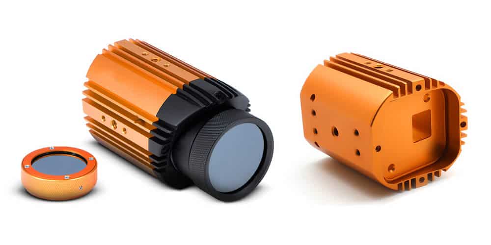
Components such as lens barrels, mirror mounts, optomechanical stages, and sensor housings benefit from multi-axis machining, which ensures alignment of optical bores and mounting surfaces within microns. Material selection is driven by thermal stability, weight, corrosion resistance, and compatibility with optical coatings or adhesives. Nylon and ABS are typically used in non-critical or prototype assemblies where cost and speed are prioritized, while aluminum and steel dominate in production-grade precision optics systems.
From CAD to Part: The Process
Honyo Prototype CNC Precision Optics Workflow
Our CNC precision optics process integrates advanced manufacturing with rigorous technical validation to deliver components meeting stringent optical performance requirements. The workflow begins when a client uploads a native CAD file (STEP, IGES, or native SOLIDWORKS) through our secure customer portal. This file must include critical optical specifications: surface form tolerances (e.g., λ/4 @ 632.8nm), surface roughness (e.g., <5Å RMS), material type (e.g., N-BK7, Fused Silica, ZnSe), and coating requirements. Incomplete specifications trigger an automated notification for clarification before proceeding.
AI-Powered Technical Quoting
The uploaded CAD undergoes immediate analysis via our proprietary AI engine, which cross-references geometric complexity, material properties, and tolerance demands against historical production data. Unlike generic quoting systems, our AI evaluates optical-specific constraints:
Feasibility of achieving required surface figure and finish via CNC diamond turning or milling
Material stress risks during machining (e.g., crystalline structure challenges in CaF₂)
Metrology validation pathways for specified tolerances
The output is a formal technical quotation within 4 business hours, detailing not only cost and lead time but also preliminary process recommendations and potential DFM flags. This phase includes a preliminary risk assessment score (1-5 scale) for critical features.
Optical-Specific DFM Analysis
All quotes undergo mandatory Design for Manufacturability (DFM) review by our optical engineering team. This is not a checklist but a collaborative technical dialogue focused exclusively on optical performance preservation. Key considerations include:
| Feature Category | Standard CNC DFM Focus | Honyo Optical DFM Focus |
|---|---|---|
| Geometry | Draft angles, wall thickness | Edge thickness for mounting stress, clearance for metrology probes |
| Tolerances | ±0.05mm dimensional | Surface power (fringes), irregularity (λ/20), centering (arcsec) |
| Material | Machinability, cost | Homogeneity requirements, birefringence sensitivity, coating adhesion |
| Metrology | Caliper/ CMM accessibility | Interferometer path clearance, reference surface definition |
The DFM report identifies actionable optimizations: adjusting edge profiles to prevent chipping, modifying datums for alignment during coating, or recommending stress-relief steps for brittle materials. Clients receive annotated CAD markups and a revised technical proposal within 72 hours of DFM initiation.
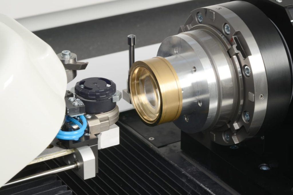
Precision Production Execution
Approved designs enter production in our ISO Class 7 cleanroom environment using dedicated optical CNC platforms (e.g., Moore Nanotech 350FG, Precitech Optimum 2800). The process sequence is strictly controlled:
Rough Machining: High-speed milling with diamond-coated tools to achieve near-net shape while minimizing subsurface damage
Fine Machining: Sub-aperture deterministic finishing (e.g., MRF, IBF) for λ/10 surface accuracy and <2Å roughness
In-Process Metrology: Real-time verification via Zygo interferometers and white-light profilometers after each critical stage
Stress Relief: Annealing cycles for crystalline materials per MIL-O-13830A standards
All environmental parameters (temperature ±0.5°C, humidity 45±5% RH) are logged to correlate with metrology results. Production batches include witness samples for coating validation.
Verified Delivery Protocol
Final inspection generates a comprehensive test report per ISO 10110, including:
Full-aperture interferometry maps (power, irregularity, RMS)
Scatterometry data for surface roughness
Dimensional verification of mechanical interfaces
Coating performance metrics (if applicable)
Components are packaged in class 100 VCI bags with desiccant, mounted in custom foam cradles, and shipped in shock-monitoring containers. Delivery includes full traceability: material certificates, process logs, and metrology datasets. Typical lead time from DFM sign-off to shipment is 15-25 business days for prototypes, with expedited optical polishing options available.
This end-to-end process ensures optical components meet functional performance targets while minimizing program risk through embedded technical validation at every phase. We maintain AS9100 and ITAR compliance for defense and aerospace applications.
Start Your Project

For high-precision CNC optical components, partner with Honyo Prototype for tight tolerances, superior surface finishes, and rapid turnaround. Our Shenzhen-based manufacturing facility leverages advanced CNC machining and metrology to deliver optical elements that meet exacting specifications for aerospace, medical, and industrial applications.
Contact Susan Leo at [email protected] to discuss your project requirements and receive a competitive quote.
🚀 Rapid Prototyping Estimator
Estimate rough cost index based on volume.