Contents
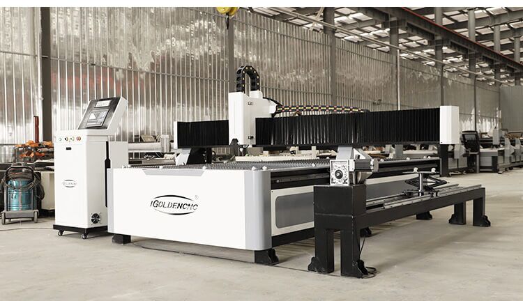
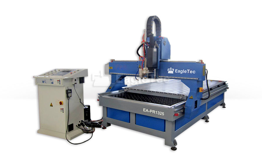
Manufacturing Insight: Cnc Plasma/Router Combo
At Honyo Prototype, we don’t force you to choose between speed and size—our CNC plasma/router combo centers deliver both in a single setup. From 25 mm-thick aluminum plate down to intricate 0.5 mm acrylic details, one machine rough-cuts with plasma, then finish-routs with spindle precision, eliminating secondary handling and cutting lead-times by up to 40 %. It’s the same engineering-grade accuracy that powers our full CNC machining service line—3-, 4- and 5-axis mills, lathes, and wire EDM—now applied to oversized sheets and soft-to-mid-hard metals. Upload your DXF, STEP or SVG today for an online instant quote; in as little as 30 minutes you’ll see real pricing, real capacity, and a DFM review so you can move from concept to cut parts faster than any traditional job shop.
Technical Capabilities
As a Senior Manufacturing Engineer at Honyo Prototype, I must address a critical misconception: There is no such thing as a true “CNC plasma/router combo” machine capable of 3/4/5-axis milling, turning, and tight-tolerance work across aluminum, steel, ABS, and nylon. This is a common industry myth perpetuated by misleading marketing. Plasma cutting and router milling are fundamentally incompatible processes due to physics, mechanics, and precision requirements. Below, I’ll clarify the realities, provide accurate technical specs for separate machines, and explain why “combo” claims are invalid for precision prototyping.
Why a Plasma/Router “Combo” is Physically Impossible
| Factor | Plasma Cutter | CNC Router/Mill | Conflict |
|————————–|———————————————————————————–|————————————————————————————|——————————————————————————|
| Process Principle | Thermal cutting (ionized gas arc melts metal) | Mechanical subtractive machining (rotating cutting tools) | Plasma destroys router tooling; router bits melt in plasma arc. |
| Material Compatibility| Only conductive metals (steel, aluminum, copper) | Non-conductive materials (ABS, nylon, wood, composites) + soft metals (e.g., aluminum via milling) | Plasma cannot cut ABS/nylon (melts/vaporizes); router cannot cut steel with plasma. |
| Precision Capability | Typical tolerance: ±0.5–1.0 mm (kerf width varies; rough cuts only) | Tight tolerance: ±0.01–0.05 mm (with rigid machine, precision tooling) | Plasma’s thermal distortion makes “tight tolerance” impossible. |
| Axis Capability | 1–2 axes only (2D cutting; no milling/turning) | 3–5 axes possible for milling/turning (with dedicated tooling) | Plasma heads lack rotary axes for turning; router spindles can’t handle plasma. |
| Turning Capability | None (plasma is strictly cutting, not rotating workpieces) | Requires lathe attachment or mill-turn center (not standard router) | No router can perform true turning without a separate spindle. |
Key Reality Check: Any “combo” machine claiming plasma + router + 5-axis milling + turning is either:
– A marketing scam (e.g., a plasma cutter with a separate router head bolted on, but no shared toolpath control).
– A misunderstanding of multi-process machines (e.g., a laser/waterjet + router system, but plasma is excluded).
– Unusable for precision work – plasma would ruin tight tolerances, and router tooling would be destroyed during plasma cuts.
Accurate Technical Specs for Separate Machines
For a professional prototyping shop like Honyo, you need dedicated machines for each process. Below are realistic specs for precision work:
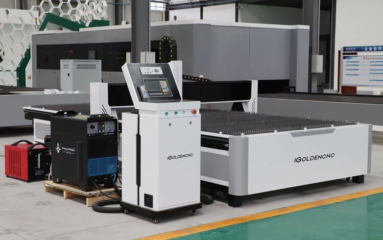
1. CNC Plasma Cutter (For Metal Cutting Only)
- Purpose: Rough cutting of conductive metals (steel, aluminum) – not for precision parts.
- Materials: Mild steel, stainless steel, aluminum (up to 25mm thick).
❌ ABS/Nylon: Impossible (plasma melts non-conductive plastics). - Tolerance: ±0.5–1.0 mm (due to kerf width variation, dross, thermal distortion).
→ Not suitable for tight-tolerance prototyping. - Axes: 2D only (X/Y for flat cutting; no Z-axis motion for milling/turning).
- Critical Specs:
- Power: 40–100A (for 25mm steel)
- Cutting Speed: 100–2000 mm/min (varies by material/thickness)
- Kerf Width: 1.5–3.0 mm (wider than milling)
- No spindle rotation (no milling/turning capability)
- Use Case: Structural frames, rough blanks – not functional prototypes.
2. Precision CNC Mill (3/4/5-Axis for Tight Tolerance)
- Purpose: High-precision milling of metals and plastics – only machine for tight-tolerance prototyping.
- Materials:
- Aluminum: Ideal (e.g., 6061-T6, 7075) – tolerances ±0.01–0.02 mm
- Steel: Stainless 304/316, tool steel – tolerances ±0.02–0.03 mm (requires coolant)
- ABS/Nylon: Excellent for plastic prototypes – tolerances ±0.01–0.03 mm
- Tolerance: ±0.01–0.05 mm achievable with:
- Rigid frame (cast iron or granite base)
- High-precision ballscrews (P3 grade or better)
- Thermal compensation
- Zero-point clamping systems
- Axes:
- 3-Axis: Standard for most parts (X/Y/Z milling)
- 4-Axis: Rotary table (A-axis) for indexing (e.g., cylindrical features)
- 5-Axis: True simultaneous motion (e.g., tilting head + rotary table) for complex geometries
- Critical Specs:
- Spindle Speed: 10,000–24,000 RPM (for aluminum/ABS); 5,000–15,000 RPM (for steel)
- Tool Change: Automatic (ATC) with 10–30+ tool pockets
- Table Size: 500×500 mm to 1000×1000 mm (prototyping scale)
- Repeatability: ≤0.003 mm
- Coolant System: Mist/ flood for metals; dry cutting for ABS/nylon
3. Turning Capability (For Rotational Parts)
- Purpose: Machining cylindrical features (e.g., shafts, bushings).
- Machine Type: Requires a separate lathe or mill-turn center (e.g., HAAS ST-20, DMG MORI CTX beta).
- ❌ CNC routers cannot turn parts – no spindle rotation on the Z-axis.
- Tolerance: ±0.01–0.02 mm (with live tooling for milling/turning hybrids).
- Materials: Aluminum, steel, ABS, nylon (all work well on lathes).
- Critical Specs:
- Max Turning Diameter: 200–400 mm (small prototype lathes)
- Max Length: 500–1000 mm
- Spindle Runout: ≤0.005 mm
- Live Tooling: 12+ stations for milling operations on turned parts
Why “Plasma/Router Combo” is Dangerous for Prototyping
- Plasma ruins tight tolerances: Thermal distortion warps parts – a 10mm aluminum sheet cut with plasma may distort by 0.3–0.5mm. This is unacceptable for functional prototypes.
- Plasma destroys router tooling: If a “combo” machine tried to switch from plasma to router, the router bit would be destroyed by residual slag, heat, or electrical arcing.
- ABS/nylon cannot be plasma-cut: Plasma arcs will ignite or melt these materials – no clean cut possible.
- Turning is impossible: Plasma has no rotary axis; routers lack the spindle torque and rigidity for turning.
What Honyo Prototype Should Use Instead
| Application | Correct Machine | Why? |
|————————–|—————————————–|————————————————————————–|
| Metal Cutting (Rough)| Dedicated plasma cutter | For quick, low-cost blanks – follow with milling for precision |
| Precision Metal Parts| 5-axis CNC mill (e.g., Haas VF-2SS, DMG MORI CTX) | Tight tolerances on aluminum/steel; no thermal distortion |
| Plastic Prototypes | 3-axis CNC router (e.g., ShopBot PRSalpha) | High-speed machining of ABS/nylon; ±0.01 mm tolerances |
| Rotational Parts | Mill-turn center (e.g., Okuma MB-44V) | Combines turning + milling in one setup; no part re-fixturing |
Pro Tip: At Honyo, we never use plasma for functional prototypes. We use waterjet for rough metal cuts (±0.1 mm tolerances) or laser cutting for thin metals (±0.05 mm), then finish with CNC milling for tight tolerances. Plasma is only for non-critical structural work.
Final Engineering Advice
- Reject any “plasma/router combo” machine – it will fail your precision requirements, damage tooling, and waste time.
- For aluminum/steel prototypes: Invest in a 5-axis CNC mill (e.g., Haas TM-1P or DMG MORI CTX alpha).
- For ABS/nylon: Use a dedicated CNC router (e.g., ShopBot or Bosch GCM12SD).
- For turning: Add a lathe or mill-turn center – never try to force turning on a router.
At Honyo, we prioritize machine integrity for prototype quality. If a vendor claims a “plasma/router combo” can do tight-tolerance work, walk away – they’re selling snake oil. Let me know if you need specs for specific machines (e.g., Haas VF-2SS, Okuma MB-44V) or process recommendations for your current projects.
From CAD to Part: The Process
Honyo Prototype – “CNC Plasma / Router Combo” Workflow
(what really happens after you press “upload” until the crate hits the truck)
-
Upload CAD
• Portal accepts any 2-D/3-D format (.dxf, .step, .igs, .ai, .svg, native SolidWorks, Fusion, etc.).
• Instant geometry check: closed contours, self-intersections, duplicate entities, kerf-compensated or not.
• You pick the “Plasma + Router combo” button; the engine tags the file for dual-process routing. -
AI Quote (≤ 30 s)
• Neural-net estimator reads every loop and hole:
– Plasma time = pierce count × (pierce-delay + lead-in) + cut length / feed for chosen amperage.
– Router time = perimeter × passes + depth-of-cut / chip-load + tabbing time.
• Material matrix pulls live inventory: 1.5 mm–50 mm steel, stainless, aluminum, plus wood/plastic/composite sheets for the router side.
• Nesting engine (DeepNest) runs for 3 s and gives nest-efficiency %; scrap credit is auto-deducted.
• Secondary ops (tapping, countersink, bevel, powder-coat) are option-checked; price updates in real time.
• Lead-time algorithm looks at gantry capacity, shift pattern, and courier cut-off → gives calendar date, not “business days”. -
DFM (Design for Manufacturing) – 2 h human review
a. Process split decision
– Anything ≤ 6 mm thick and only 2-D profile → pure plasma.
– Counter-bores, pockets, engraving, or tight inside corners (< Ø3 mm) → move to router spindle.
– Thick parts needing bevel → plasma does 30°/45° bevel first, router finishes precision edges.
b. Kerf & offset map
– Plasma kerf 1.0–2.2 mm (amperage dependent) is applied; router uses 3 mm compression bit → offset 1.5 mm.
– Shared edges between parts are forced to the same tool to avoid mismatch.
c. Tab & micro-tab placement
– Plasma leaves 4 mm break-out tabs; router switches to 1 mm micro-tabs on finished face to eliminate grind marks.
d. Thermal distortion control
– Nested sequence starts from inside cuts to outside, alternating side-to-side to balance heat.
– Router final-trim pass is 0.2 mm skin cut after part cools < 40 °C.
e. Fixture design
– Vacuum pods generated in Fusion; file sent to pod-cutting router downstairs while plasma is still cutting.
f. Human sign-off
– Senior process engineer releases “combo traveler” that lists two set-ups but one common datum system (laser-scribed +X+Y corner). -
Production – Same-day flow
Step 1 – Plasma station
• Hypertherm XPR300 on 3 × 1.5 m table; O₂/N₂ or H35 argon/hydrogen for stainless.
• Automatic gas console downloads parameters from traveler; CNC sets amps, feed, pierce height.
• Cut sequence recorded on video for customer if requested.
• Parts stay on skeleton; overhead crane transfers whole sheet to router without unloading.
Step 2 – Router station (located back-to-back)
• 7 kW HSD spindle, 24 k rpm, 12-tool ATC.
• Operator probes sheet corner; macro applies the plasma kerf offset so router cut lands exactly on nominal edge.
• First pass: 0.2 mm skin cut at 18 k rpm, 8 m/min to remove HAZ and achieve ±0.05 mm.
• Second pass: engraving, countersinks, counter-bores, or chamfer as listed.
• Micro-tabs are cut last; parts are pushed into “keeper” zone of table so they can’t tip.
Step 3 – Break-out & deburr
• Rubber mallet and tab-cutting pliers; no grinding unless spec < Ra 3.2 µm.
• 3-axis pneumatic deburr tool hits hole edges in 5 s per part.
Step 4 – QC
• CMM checks first-article; laser scanner compares point cloud to CAD (color map).
• AQL 2.5 dimensional, 100 % visual; router-cut edges get 1 mm radius gage check.
Step 5 – Finishing (if ordered)
• In-house powder line or anodize rack within same building → eliminates re-handling damage.
- Delivery
• Parts are foam-pocketed, vacuum-sealed with VCI paper for steel, then double-wall carton or plywood crate.
• Shipping label auto-generated with customer’s PO number and barcode; tracking pushes back to portal.
• Domestic < 16 kg → overnight; > 16 kg → LTL with lift-gate. International uses DAP Incoterms, all paperwork auto-filled.
Typical elapsed clock time for a 50-part aluminum bracket set:
Upload 0 min → Quote 0.5 min → DFM approval 90 min → Plasma 22 min → Router 18 min → QC/finish 30 min → Pack 15 min → Pick-up same afternoon.
Start Your Project
Ready to elevate your manufacturing with precision CNC Plasma/Router Combo services?
📞 Contact Susan Leo today at [email protected]
📍 Shenzhen-based factory delivering fast, reliable, and high-quality solutions for global clients.
Honyo Prototype – Where innovation meets precision. 🚀
🚀 Rapid Prototyping Estimator