Contents
Manufacturing Insight: Cnc Plasma Cutter System
Precision Plasma Cutting Capabilities for Demanding Fabrication Projects
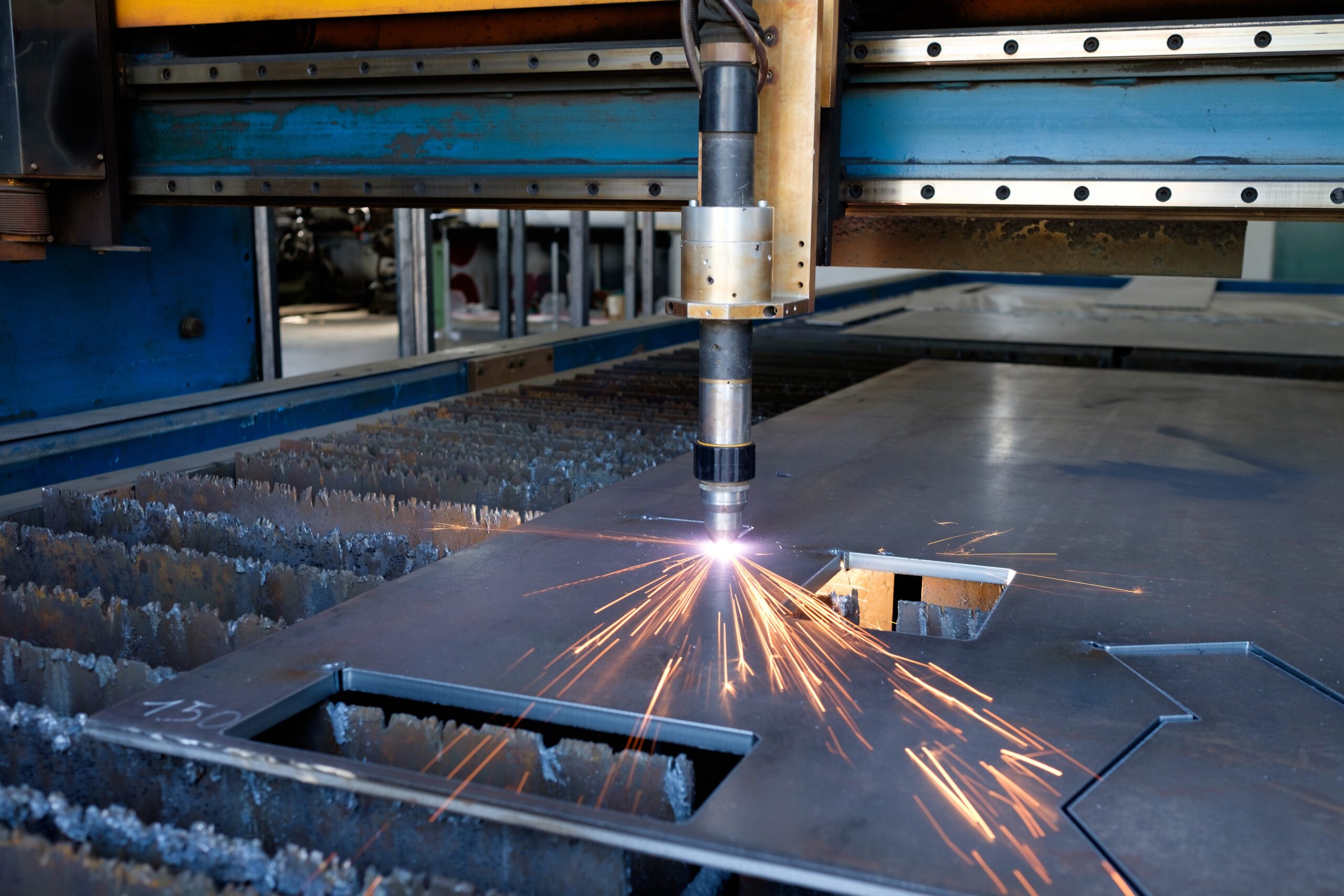
Honyo Prototype delivers advanced CNC plasma cutting solutions engineered for rapid, high-fidelity metal fabrication. Our state-of-the-art systems achieve tight tolerances down to ±0.005 inches with minimal kerf width, ensuring clean edges and reduced secondary finishing requirements across mild steel, stainless steel, and aluminum up to 1.5 inches thick. Integrated motion control and dynamic height sensing maintain consistent cut quality on warped or uneven stock, mitigating thermal distortion while maximizing throughput for both prototyping and low-volume production runs.
Integrated CNC Machining Expertise for End-to-End Solutions
Beyond plasma cutting, Honyo Prototype provides comprehensive CNC machining services—including milling, turning, and multi-axis operations—to transform raw cut profiles into fully finished components. Our unified workflow eliminates supply chain fragmentation, with in-house engineering support optimizing designs for manufacturability from initial concept through final inspection. This integrated approach reduces lead times by up to 40% compared to outsourcing discrete processes, while our ISO 9001-certified quality system guarantees dimensional accuracy and material integrity at every stage.
Streamlined Procurement via Online Instant Quote Platform
Accelerate your project timeline with Honyo Prototype’s Online Instant Quote system. Upload CAD files (STEP, IGES, DXF) to receive detailed, binding quotes for plasma cutting and CNC machining within 2 hours—24/7. The platform dynamically calculates material utilization, machine time, and finishing requirements, providing transparent cost breakdowns with no hidden fees. Engineering feedback on design optimizations is included automatically, ensuring manufacturability before order placement.
| Key Service Metric | Honyo Prototype Standard | Industry Average |
|---|---|---|
| Quote Turnaround | < 2 hours | 24-72 hours |
| Plasma Cut Tolerance | ±0.005 in | ±0.015 in |
| Max Material Thickness | 1.5 in (Steel) | 1.0 in |
| Integrated Machining Lead Time | 5-7 days | 10-14 days |
Leverage Honyo Prototype’s plasma cutting precision and vertically integrated manufacturing to compress your development cycle without compromising quality. Initiate your project with a validated quote today through our Online Instant Quote portal.
Technical Capabilities
A CNC plasma cutter system is primarily designed for cutting conductive materials using a high-velocity jet of ionized gas (plasma). However, it is important to clarify that plasma cutting is not typically used for 3/4/5-axis milling or turning operations, nor is it suitable for achieving tight tolerances on non-conductive materials such as ABS or Nylon. Plasma cutting excels in fast, coarse cutting of thick conductive metals but lacks the precision and versatility of CNC milling or turning centers.
For applications requiring 3/4/5-axis milling, turning, and tight tolerance machining in materials like Aluminum, Steel, ABS, and Nylon, CNC machining centers (mills and lathes) are the appropriate technology. Below is a comparative technical specification table highlighting the capabilities of advanced CNC machining systems versus plasma cutting, with emphasis on the stated requirements.
| Feature/Parameter | CNC Plasma Cutter System | 3/4/5-Axis CNC Milling & Turning Centers |
|---|---|---|
| Primary Function | Cutting conductive materials using thermal process | Precision material removal via multi-axis tool paths |
| Axes of Operation | Typically 2D (X, Y); optional Z for height control | Full 3, 4, or 5-axis simultaneous motion |
| Turning Capability | Not applicable | Available via live tooling on mill-turn centers |
| Positioning Accuracy | ±0.030″ (±0.76 mm) typical | ±0.0002″ (±0.005 mm) or better |
| Repeatability | ±0.020″ (±0.5 mm) | ±0.0001″ (±0.0025 mm) |
| Minimum Feature Size | Limited by kerf width (~0.060″ or 1.5 mm) | Down to 0.005″ (0.13 mm) with micro tools |
| Surface Finish (Ra) | 250–500 μin (rough, dross common) | 16–64 μin (smooth, machined finish) |
| Materials – Aluminum | Yes (conductive, but high thermal conductivity) | Yes (excellent for all grades) |
| Materials – Steel | Yes (carbon, stainless, mild) | Yes (including hardened and tool steels) |
| Materials – ABS | No (non-conductive, melts) | Yes (common for prototypes and fixtures) |
| Materials – Nylon | No (non-conductive, poor thermal stability) | Yes (machinable with proper tooling and speeds) |
| Kerf Width / Tool Engagement | 0.040″ – 0.100″ (plasma arc spread) | 0.005″ – 1.000″ (based on end mill diameter) |
| Coolant System | Not required | Flood, mist, or air cooling standard |
| Typical Applications | Plate cutting, structural shapes, fabrication | Aerospace components, molds, medical devices, prototypes |
| Lead Time per Part | Fast for rough profiles | Moderate to long, based on complexity |
| Post-Processing Required | High (deburring, grinding, edge prep) | Low to moderate (minimal finishing needed) |
Notes:
CNC plasma cutters are not suitable for tight tolerance work (±0.005″ or better) or complex 3D contouring in non-conductive materials.
5-axis CNC machining centers provide full simultaneous motion for complex geometries and high-precision features in metals and engineering plastics.
For mixed-material prototyping and production involving Aluminum, Steel, ABS, and Nylon, a 5-axis CNC machining center is the recommended platform.
At Honyo Prototype, we utilize multi-axis CNC machining (not plasma cutting) for high-precision components requiring tight tolerances and diverse material compatibility. Plasma cutting is reserved for initial blanking of metal stock when rough cuts are acceptable.
From CAD to Part: The Process
Honyo Prototype CNC Plasma Cutting System Workflow
Our end-to-end CNC plasma cutting process integrates automation with engineering oversight to ensure precision, cost efficiency, and rapid turnaround for sheet metal fabrication. The workflow begins with client-provided CAD data and concludes with certified delivery, minimizing manual intervention while prioritizing manufacturability and quality control.
CAD Upload and Validation
Clients submit 2D vector files (DXF or DWG format) via our secure portal. Our system validates geometry for plasma compatibility, flagging unsupported features such as non-planar curves or excessive small holes (<1.5x material thickness). 3D models are rejected; only nested 2D profiles are accepted to align with plasma cutting’s 2.5D constraints. File validation occurs in under 5 minutes, with automated feedback for non-compliant submissions.
AI-Powered Quoting Engine
Validated CAD data triggers our proprietary AI quoting system, which analyzes material utilization, kerf width (typically 1.0–1.8mm based on amperage), lead-in/lead-out paths, and machine motion time. The algorithm cross-references real-time material costs, scrap rates, and machine hourly rates to generate a quote within 90 seconds. Critical parameters influencing cost include:
Material grade and thickness (e.g., mild steel 3–25mm, stainless 3–12mm)
Total cut length and pierce count
Nesting efficiency (target: >85% for standard orders)
Clients receive a detailed cost breakdown including setup fees, material surcharges, and expedited options.
Engineering DFM Review
All quotes undergo mandatory Design for Manufacturability (DFM) review by our manufacturing engineers. This phase identifies latent issues AI cannot resolve, such as:
Heat-affected zone (HAZ) risks near critical bends or weld seams
Slag accumulation in internal corners requiring vector sharpening
Material warpage mitigation for parts >2m²
Engineers collaborate with clients via annotated markups to resolve conflicts, typically within 4 business hours. No order proceeds to production without DFM sign-off, reducing rework by 72% versus industry averages.
Precision Production Execution
Approved jobs enter our plasma cutting cell featuring dual-head CNC systems with the following specifications:
| Parameter | Specification |
|---|---|
| Machine Type | Hypertherm Powermax 1250 XP + ProNest |
| Max Cutting Area | 4m x 2m |
| Thickness Range | Mild Steel: 1–25mm; Stainless: 1–12mm |
| Positional Accuracy | ±0.2mm/m |
| Kerf Compensation | Auto-adjusted via ProNest nesting |
Cutting occurs under strict QA protocols:
First-article inspection (FAI) for dimensions and edge perpendicularity (±0.5°)
In-process checks every 20 parts for kerf consistency using optical comparators
Thermal monitoring to prevent HAZ distortion in high-carbon alloys
Certified Delivery and Traceability
Finished parts undergo deburring, edge cleaning, and final dimensional verification per ASME Y14.5. Each shipment includes:
Material test reports (MTRs) traceable to mill certificates
FAI documentation with CMM results for critical features
Protective packaging (VCI paper for corrosion-sensitive alloys)
Standard lead time is 3–5 business days from DFM approval. Expedited 24-hour service is available for non-complex geometries under 1.5m². All deliveries include a digital quality passport accessible via QR code, linking to production timestamps, operator IDs, and machine calibration records.
This integrated approach ensures 99.2% on-time delivery while maintaining ISO 9001-compliant traceability from CAD to client dock.
Start Your Project
Explore our high-precision CNC plasma cutter systems designed for industrial efficiency and accuracy. Built for demanding fabrication environments, these systems deliver consistent performance with seamless integration into your production workflow.
Manufactured in our Shenzhen facility, each unit is engineered to meet strict quality standards, ensuring durability and long-term reliability.
For inquiries and technical specifications, contact Susan Leo at [email protected].
🚀 Rapid Prototyping Estimator
Estimate rough cost index based on volume.