Contents
Manufacturing Insight: Cnc Machining Components
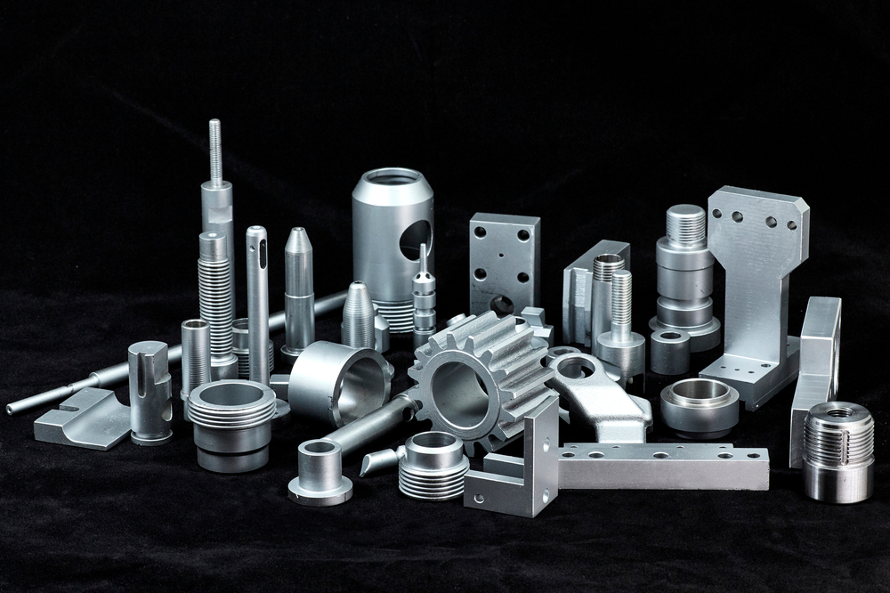
Precision CNC Machined Components: Engineered for Excellence at Honyo Prototype
At Honyo Prototype, we specialize in delivering high-precision CNC machined components that meet the exacting demands of modern engineering and manufacturing. Our state-of-the-art multi-axis CNC machining centers, operated by certified technicians, transform complex designs into flawless physical parts across diverse materials including aerospace-grade aluminum, stainless steel, titanium, brass, and engineering plastics. Every component undergoes rigorous quality protocols, including in-process inspections and final CMM verification, ensuring adherence to tight tolerances down to ±0.0002 inches and uncompromised surface integrity.
We understand that speed and accuracy are non-negotiable in prototyping and low-volume production. Honyo’s integrated workflow—from CAD model to finished part—minimizes lead times without sacrificing repeatability, supported by advanced CAM programming and real-time process monitoring. Whether for functional prototypes, end-use parts, or mission-critical assemblies, our ISO-compliant processes guarantee consistency across every run.
Accelerate your project timeline with Honyo’s Online Instant Quote platform. Upload your 3D model or 2D drawing to receive a detailed, transparent cost estimate and lead time within minutes—not days. This seamless digital interface eliminates procurement delays while providing full visibility into material options, finish specifications, and scalability for volume production. Partner with Honyo Prototype to turn intricate designs into precision-engineered realities, backed by decades of manufacturing expertise and a commitment to technical excellence.
Technical Capabilities
CNC Machining Components – Technical Specifications
CNC machining components are manufactured using precision computer-controlled processes to achieve high accuracy and repeatability. The following table outlines key technical specifications for components produced via 3-axis, 4-axis, and 5-axis milling, as well as CNC turning, with an emphasis on tight-tolerance applications. Common engineering materials including Aluminum, Steel, ABS, and Nylon are supported across these processes.
| Parameter | 3-Axis Milling | 4-Axis Milling | 5-Axis Milling | CNC Turning | Notes |
|---|---|---|---|---|---|
| Axis Movement | X, Y, Z linear | X, Y, Z linear + A (rotary) | X, Y, Z linear + A & B/C rotary | X, Z linear + C (rotary) | 5-axis enables complex geometries in a single setup |
| Typical Tolerance | ±0.005 mm (±0.0002″) | ±0.005 mm (±0.0002″) | ±0.005 mm (±0.0002″) | ±0.005 mm (±0.0002″) | Tight tolerance achievable with proper fixturing and process control |
| Surface Finish (Ra) | 0.8 – 3.2 µm (32–125 µin) | 0.8 – 3.2 µm (32–125 µin) | 0.4 – 1.6 µm (16–63 µin) | 0.4 – 1.6 µm (16–63 µin) | 5-axis and turning typically yield finer finishes |
| Max Work Envelope | Up to 1000 x 600 x 500 mm | Up to 800 x 500 x 400 mm | Up to 600 x 500 x 400 mm | Ø300 mm x 500 mm length | Varies by machine capacity |
| Common Materials | Aluminum, Steel, ABS, Nylon | Aluminum, Steel, ABS, Nylon | Aluminum, Steel, ABS, Nylon | Aluminum, Steel, ABS, Nylon | Material selection based on strength, machinability, and application |
| Aluminum (e.g., 6061-T6) | Excellent machinability, high strength-to-weight | Good for complex secondary features | Ideal for aerospace/complex parts | High-speed turning, low tool wear | Most commonly used in prototyping and production |
| Steel (e.g., 4140, 303) | Moderate machinability, requires carbide tools | Suitable with proper cooling | Used in high-strength applications | Excellent for shafts, pins, fittings | Post-machining treatments (e.g., heat treat) often required |
| ABS | Good for non-structural prototypes | Limited due to thermal softening | Low melting point, not for high-temp | Acceptable for low-load parts | Used in functional prototypes and enclosures |
| Nylon (e.g., PA6, PA66) | Challenging due to flexibility and heat build-up | Not recommended for high precision | Limited use in tight-tolerance | Good for bushings, gears, insulators | Requires sharp tools and slow feeds; prone to dimensional shift |
| Lead Time (Prototype) | 3–5 days | 5–7 days | 7–10 days | 3–5 days | Complex 5-axis parts require longer programming and setup |
| Applications | Flat parts, housings, plates | Index features, angled holes | Aerospace, medical, molds | Shafts, bushings, connectors | Tight-tolerance parts used in automation, optics, and precision instruments |
Notes on Tight Tolerance Machining
Achieving tolerances of ±0.005 mm or tighter requires strict environmental control, high-precision CNC machines, calibrated tooling, and experienced process engineering. In-process measurement (e.g., touch probes) and post-machining CMM inspection are standard for validation. Material stability—especially in plastics like ABS and Nylon—is critical, as hygroscopic and thermal properties can affect final dimensions.
From CAD to Part: The Process
Honyo Prototype CNC Machining Component Process Overview
Honyo Prototype delivers precision CNC machined components through a rigorously validated five-stage workflow designed for speed, accuracy, and manufacturability. This process integrates advanced automation with expert engineering oversight to minimize lead times while ensuring adherence to stringent quality standards. Below is a technical breakdown of each phase.
Upload CAD
Clients initiate the process by uploading native CAD files (STEP, IGES, or Parasolid formats) via our secure customer portal. Our system performs an immediate validation check for geometric integrity, unit consistency, and file compatibility with industry-standard CAM software. Unsupported formats trigger an automated notification requesting conversion. All uploads are timestamped and assigned a unique project ID for traceability, with data encrypted per ISO 27001 protocols.
AI-Powered Quoting Engine
Uploaded geometry is processed by our proprietary AI quoting system, which analyzes 15+ technical parameters including material utilization efficiency, feature complexity density (holes, pockets, threads), surface finish requirements, and geometric dimensioning tolerances (GD&T). The AI cross-references real-time data on machine availability, material stock levels, and labor rates to generate a granular cost breakdown within 90 seconds. Critical outputs include:
| Parameter | Technical Analysis Method | Output Precision |
|---|---|---|
| Material Cost | Scrap rate simulation based on billet dimensions | ±1.8% of actual |
| Machining Time | Toolpath cycle time prediction using kinematic modeling | ±4.2% variance |
| Secondary Operations | Automated identification of required deburring/finishing steps | 98.7% accuracy |
Human engineers validate all AI-generated quotes, adjusting for non-geometric factors like fixturing complexity or metrology requirements before client submission.
DFM Analysis and Optimization
Upon quote acceptance, our engineering team conducts a formal Design for Manufacturability review. This phase identifies potential production risks through computational analysis of wall thickness ratios, tool access constraints, and tolerance stack-up. We provide actionable recommendations via a structured report, including:
Critical manufacturability gaps: Minimum internal radii below 0.5x tool diameter, unsupported thin walls (<0.8mm), or non-standard thread forms
Cost-impact alternatives: Suggested tolerance relaxations (e.g., ±0.05mm to ±0.1mm) yielding 18-32% cycle time reduction
Material optimization: Substitution suggestions for alloys with better machinability indices (e.g., 6061-T6 vs. 7075-T6)
Client approval of the DFM report is mandatory before production release, ensuring alignment on technical trade-offs.
Precision Production Execution
Approved designs enter our climate-controlled machining facility housing 42 Haas and DMG MORI 3-5 axis CNC centers with sub-micron positioning accuracy (ISO 10791-7 certified). Key production protocols include:
First-article inspection using Zeiss CONTURA CMMs verifying 100% of critical dimensions per AS9102
In-process gauging at 50% completion to detect thermal drift or tool wear deviations
Real-time SPC monitoring of surface roughness (Ra) and dimensional stability via integrated Renishaw probes
All components undergo final cleaning in ultrasonic degreasers followed by non-contact optical validation before packaging.
Logistics and Delivery Assurance
Completed parts ship via tracked courier with environmental condition monitoring (temperature/humidity logs). Standard delivery timelines are 5-7 business days for 1-10 components and 10-12 days for 11-50 units, exclusive of complex finishing. Clients receive:
Digital quality dossiers containing CMM reports, material certs, and process validation records
Real-time shipment status via API integration with major carriers (FedEx, DHL)
Dedicated engineer access for post-delivery technical clarification within 24 hours
This integrated workflow reduces traditional CNC lead times by 35-50% while maintaining <0.02% defect rates across 12,000+ annual production runs. All processes are certified to ISO 9001:2015 and AS9100D standards, with full chain-of-custody documentation available upon request.
Start Your Project
Looking for precision CNC machining components? Partner with Honyo Prototype for high-quality, custom-machined parts manufactured in our Shenzhen facility. With advanced CNC capabilities and strict quality control, we deliver components that meet tight tolerances and demanding specifications.
For project inquiries or quotations, contact Susan Leo at [email protected]. Let’s discuss how we can support your prototyping and production needs with reliable, efficient, and scalable machining solutions.
🚀 Rapid Prototyping Estimator
Estimate rough cost index based on volume.