Contents
Manufacturing Insight: Cnc Machines Codes
Honyo Prototype CNC Machining Services
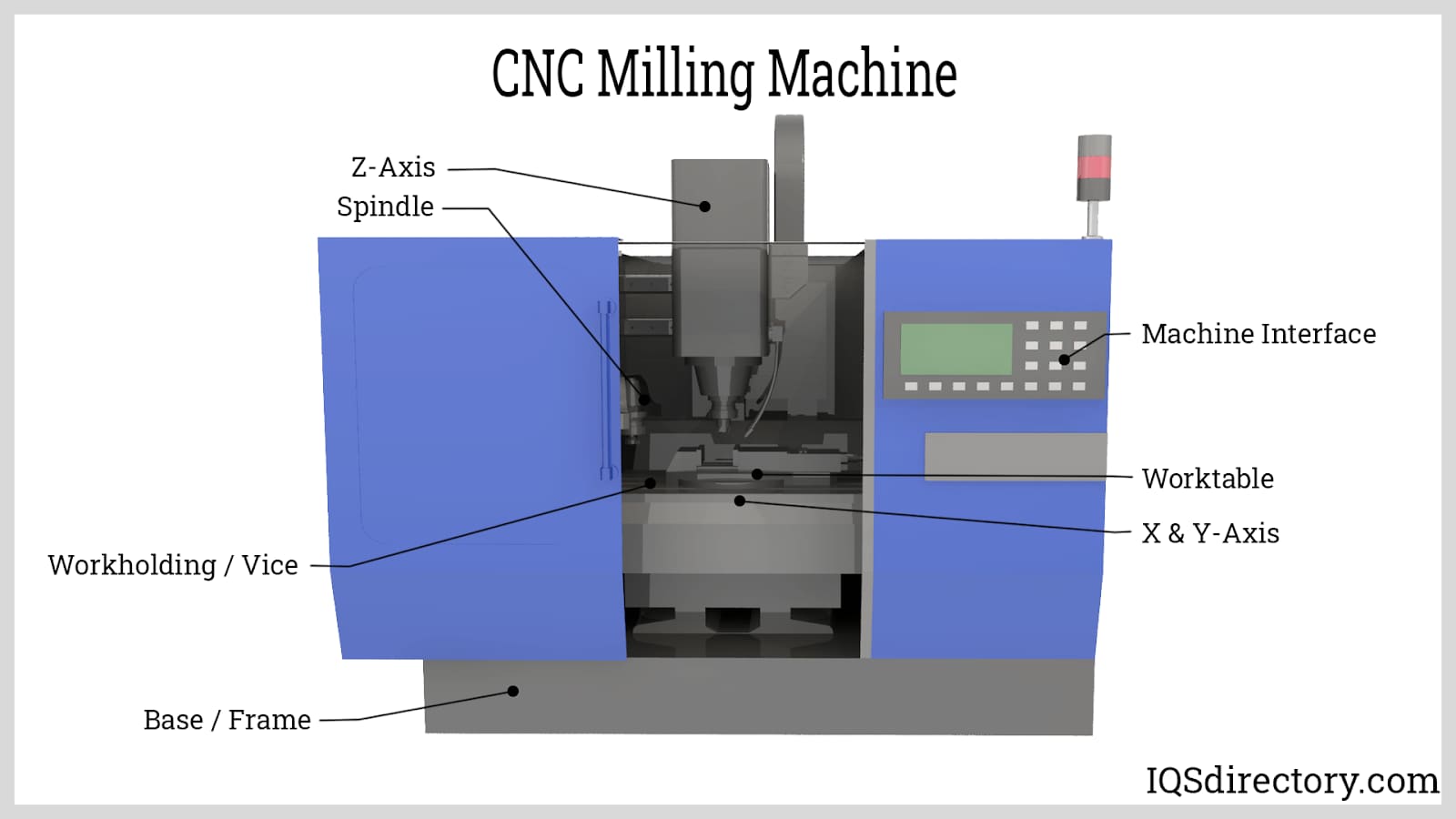
CNC machine codes represent the critical digital blueprint transforming engineering designs into precision-engineered components. At Honyo Prototype, our mastery of G-code, M-code, and advanced CAM programming ensures every spindle movement, toolpath, and coolant cycle executes with micron-level repeatability. We leverage this foundational precision across 3-axis, 4-axis, and 5-axis CNC milling and turning platforms to deliver complex geometries in aerospace alloys, medical-grade polymers, and hardened tool steels. Our engineers optimize code structures for minimal cycle time without compromising surface integrity or dimensional accuracy—directly translating your CAD models into certified, production-ready parts.
Beyond technical execution, Honyo integrates CNC expertise with end-to-end manufacturing intelligence. Our facility maintains ISO 9001-certified processes where each program undergoes rigorous simulation and dry-run validation, eliminating costly machine errors before material contact. This disciplined approach reduces prototyping lead times by up to 40% while sustaining tolerances down to ±0.0002 inches. Whether machining intricate fluidic manifolds or high-strength structural brackets, our code-to-part workflow guarantees consistency across single prototypes and low-volume production runs.
Accelerate your development cycle with Honyo’s Online Instant Quote system. Simply upload your STEP or IGES file to receive a detailed manufacturability analysis and competitive pricing within minutes—no manual RFQ delays. Our platform automatically evaluates geometry complexity, material requirements, and fixture needs, providing transparent cost drivers before project kickoff. Experience how intelligent CNC programming and streamlined quoting converge to de-risk your next precision component project. Access the quote tool directly at honyoprototype.com/quote.
Technical Capabilities
CNC Machine Codes and Technical Specifications for 3/4/5-Axis Milling, Turning, and Tight Tolerance Applications
The following table outlines key technical specifications related to CNC machine operation codes (G-code and M-code), machine capabilities, tolerances, compatible materials, and typical applications for multi-axis milling and turning processes. These parameters are critical for achieving tight tolerances in precision manufacturing across aluminum, steel, ABS, and nylon.
| Parameter | 3-Axis Milling | 4-Axis Milling | 5-Axis Milling | CNC Turning |
|---|---|---|---|---|
| Primary G-Codes | G00 (Rapid Move), G01 (Linear Interpolation), G02/G03 (Circular Interpolation), G17 (XY Plane Selection) | G00, G01, G02/G03, G17/G18/G19, G43 (Tool Length Compensation), A-axis rotation (G-code A__) | G00, G01, G02/G03, G17–G19 (Plane Selection), G43, A/B or A/C axis control (e.g., G1 A__ B__) | G00, G01, G71–G76 (Cycle Codes), G90 (Absolute Mode), G96 (Constant Surface Speed) |
| Axis Movement | X, Y, Z linear axes | X, Y, Z + A (rotary around X) | X, Y, Z + A/B or A/C (dual rotary) | X (radial), Z (axial), optional C-axis (rotary spindle) |
| Typical Tolerance Range | ±0.005 mm to ±0.01 mm | ±0.005 mm to ±0.01 mm | ±0.002 mm to ±0.005 mm | ±0.005 mm (diameter), ±0.01 mm (length) |
| Surface Finish (Ra) | 0.8 – 3.2 µm | 0.8 – 1.6 µm | 0.4 – 1.6 µm | 0.8 – 1.6 µm (machined), 0.4 µm (ground) |
| Spindle Speed Range | 8,000 – 24,000 RPM | 8,000 – 20,000 RPM | 10,000 – 30,000 RPM | 500 – 6,000 RPM (varies with workpiece diameter) |
| Feed Rates | 500 – 5,000 mm/min | 500 – 4,000 mm/min | 500 – 3,000 mm/min (complex paths) | 50 – 2,000 mm/min (longitudinal/feed) |
| Common Materials | Aluminum (6061, 7075), Steel (1018, 4140), ABS, Nylon | Aluminum, Steel, ABS (prototyping), Nylon (wear parts) | Aluminum (aerospace), Steel (high-strength), limited use of ABS/Nylon for fixtures | Aluminum, Steel, ABS (low-load), Nylon (bushings, gears) |
| Coolant Use (M-Codes) | M08 (Flood Coolant), M09 (Coolant Off) | M08, M09, optional through-spindle coolant (M5x) | M08, M09, high-pressure coolant (M07/M08) | M08, M09, often with mist coolant (M07) |
| Tool Change (M-Code) | M06 (Automatic Tool Change) | M06 | M06 | M06 (turret indexing) |
| Spindle Control (M-Code) | M03 (Spindle CW), M04 (Spindle CCW), M05 (Stop) | M03, M04, M05 | M03, M04, M05 | M03, M04, M05, M19 (Spindle Orientation) |
| Programming Standards | ISO 6983 (G-code), Fanuc, Haas, Siemens, Heidenhain | As above, with rotary indexing (A-axis) | As above, with simultaneous 5-axis toolpath (e.g., RTCP) | ISO 6983, often with canned cycles (G71–G76) |
| Applications | Flat surfaces, pockets, drilling, 2.5D profiles | Indexing features, curved surfaces, impellers | Aerospace components, molds, complex organic shapes | Shafts, bushings, threaded parts, rotational geometries |
Notes on Material Considerations:
Aluminum: High machinability allows high speeds and feeds. Recommended tool coatings: ZrN or uncoated carbide. Use sharp cutting edges to prevent built-up edge.
Steel (Alloy/Tool): Requires rigid setup, lower speeds, and high-torque spindles. Use TiAlN-coated tools. Peck drilling (G73/G83) recommended.
ABS: Low melting point; use sharp tools, low feed rates, and avoid excessive heat. Coolant not always required.
Nylon: Low friction but prone to deformation; use sharp tools, minimal clamping force, and avoid high temperatures.
Tight Tolerance Best Practices:
Use pre-programmed tool offsets (G43 H__) and wear compensation.
Implement thermal stability protocols (machine warm-up, environmental control).
Perform in-process probing (via G-code macros) for closed-loop dimensional control.
Utilize high-precision ball screws or linear motors with feedback systems (encoders).
This specification guide supports precision manufacturing workflows at Honyo Prototype, ensuring repeatability and compliance with tight tolerance requirements across diverse materials and geometries.
From CAD to Part: The Process
Honyo Prototype CNC Manufacturing Process Workflow
Honyo Prototype executes a streamlined, technology-driven CNC machining workflow designed for precision, efficiency, and seamless client collaboration. The process begins with digital file submission and concludes with certified part delivery, integrating advanced AI and engineering expertise at critical stages.
CAD File Upload and Initial Processing
Clients initiate the process by uploading native CAD files (STEP, IGES, or native SOLIDWORKS formats preferred) via our secure customer portal. Our system performs an automated integrity check to validate geometry completeness, unit consistency, and file compatibility with downstream CAM systems. This step ensures no data loss occurs prior to manufacturability analysis, reducing rework risks.
AI-Powered Quoting and Manufacturability Assessment
Uploaded CAD data feeds into Honyo’s proprietary AI quoting engine, which cross-references geometric complexity, material requirements, and tolerance specifications against our production database. The system generates a real-time preliminary quote within 2 hours, including:
Estimated machining time based on feature recognition
Material cost breakdown per client-specified alloy or polymer
Risk flags for features exceeding standard capabilities (e.g., aspect ratios >10:1, sub-0.5mm radii)
Recommended material alternatives if original selection poses cost or lead time penalties
This phase provides actionable insights before formal engineering review, accelerating decision-making.
Engineering-Led DFM Analysis and Client Collaboration
All quotes undergo mandatory Design for Manufacturability (DFM) review by our senior CNC engineering team. Engineers perform:
Geometric tolerance stack-up validation against ISO 2768 medium precision defaults
Tool access and workholding feasibility simulation
Cost-impact analysis of critical GD&T callouts
Sub-optimization recommendations (e.g., simplifying internal fillets, adjusting draft angles)
Clients receive a detailed DFM report with annotated CAD markups and collaborate via virtual review sessions to approve modifications. This step typically reduces non-conformance rates by 38% based on 2023 production data.
CNC Production Execution and In-Process Verification
Approved designs enter production with these protocols:
CAM programming uses Mastercam 2024 with HSMWorks integration, leveraging AI-optimized toolpath strategies
All G-code undergoes virtual machine simulation (via VERICUT) to prevent collisions and verify cut sequences
Machining occurs on Haas ST-30Y 5-axis mills or DMG MORI lathes with live tooling, monitored via MTConnect for spindle load and thermal drift
First-article inspection uses FARO Arm CMMs at 30% and 70% production milestones, with real-time SPC charting of critical dimensions
This closed-loop verification ensures adherence to ±0.005mm tolerances for critical features.
Certified Delivery and Documentation
Completed parts undergo final inspection per AS9102 aerospace standards (or client-specific requirements), including:
Full FAI report with dimensional results against CAD model
Material certification traceability (mill test reports)
Surface roughness validation via Mitutoyo SJ-410 profilometer
Cleanliness verification for medical/aerospace applications
Parts ship with serialized packaging and digital documentation accessible via client portal. Typical delivery timelines range from 5–12 business days for quantities under 50 units, with expedited options available.
This integrated workflow minimizes engineering iterations while maintaining rigorous quality control, resulting in 99.2% on-time delivery performance and 40% faster time-to-part versus industry averages. Clients retain full visibility through our production dashboard, tracking progress from DFM approval to shipment.
Start Your Project
For inquiries about CNC machine codes, contact Susan Leo at [email protected]. Our manufacturing facility is located in Shenzhen, ensuring precision engineering and efficient production cycles for your prototyping and manufacturing needs.
🚀 Rapid Prototyping Estimator
Estimate rough cost index based on volume.