Contents
Manufacturing Insight: Cnc Machine G Code List
G Code: The Precision Blueprint for Modern CNC Machining
At Honyo Prototype, we recognize G Code as the foundational language driving precision, efficiency, and repeatability in CNC manufacturing. Our comprehensive CNC machining services leverage this critical instruction set to transform complex 3D models into high-tolerance components across aerospace, medical, automotive, and industrial sectors. Every line of G Code executed on our Haas, DMG MORI, and Makino equipment is optimized for speed, accuracy, and material integrity—ensuring your prototypes and production parts meet stringent geometric and surface finish requirements.
We specialize in multi-axis milling, turning, and Swiss machining for metals including aluminum 7075-T6, titanium Ti-6Al-4V, and stainless steel 316L, as well as engineering polymers like PEEK and ULTEM. Our engineering team validates G Code programs through rigorous simulation and first-article inspection, minimizing machine downtime and scrap rates while adhering to ISO 9001:2015 standards. This technical rigor ensures your design intent is preserved from digital model to physical part, with tolerances consistently held to ±0.0002″ (5 µm).
Accelerate your path from concept to hardware with Honyo’s Online Instant Quote platform. Upload CAD files in STEP, IGES, or native formats to receive a detailed manufacturability analysis, lead time, and competitive pricing within minutes—not days. This seamless integration of engineering expertise and digital workflow empowers rapid iteration without compromising precision, making Honyo your strategic partner for on-demand CNC machining where time-to-market is non-negotiable.
Technical Capabilities
CNC Machine G Code List – Technical Specifications for 3/4/5-Axis Milling, Turning, and Tight Tolerance Applications
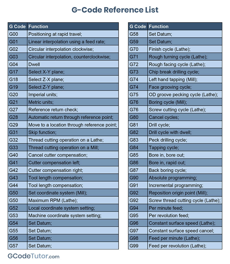
Below is a comprehensive list of commonly used G codes applicable across 3-axis, 4-axis, and 5-axis CNC milling machines as well as CNC turning centers. These codes are critical for achieving tight tolerances (±0.0005″ to ±0.005″) in precision manufacturing of materials such as Aluminum, Steel, ABS, and Nylon. The table includes functional descriptions and relevance to multi-axis and high-precision operations.
| G Code | Function Description | Relevance to 3/4/5-Axis Milling | Relevance to Turning | Material Considerations (Aluminum, Steel, ABS, Nylon) |
|---|---|---|---|---|
| G00 | Rapid positioning – moves tool at maximum speed to target coordinates | Used for non-cutting moves; essential for reducing cycle time in complex 5-axis toolpaths | Rapid traverse to position tool near workpiece | Minimizes thermal deformation in thermoplastics (ABS, Nylon); critical for maintaining precision in hardened steel |
| G01 | Linear interpolation – controlled feed rate move in straight line | Primary code for precise contouring in tight tolerance milling operations | Used for straight turning, facing, and tapering | Enables fine surface finish on Aluminum and Steel; requires stable feed to avoid chatter in Nylon |
| G02 | Circular interpolation – clockwise arc | Enables complex curved surfaces in 3D contouring (e.g., molds, aerospace parts) | Used for creating radii and fillets in part profiles | Critical for smooth finishes on Aluminum; requires rigidity when cutting high-strength steel; avoid overheating ABS |
| G03 | Circular interpolation – counterclockwise arc | Complements G02 for full 3D surface generation in multi-axis milling | Same as G02, for counter-rotational arcs | Same as G02; especially useful in high-precision Aluminum impellers or Nylon fluid components |
| G17 | Select XY plane | Default for 3-axis milling; used as reference in 4/5-axis when orienting work coordinate systems | Less relevant; turning typically uses XZ plane | Ensures correct cutter compensation for planar features in all materials |
| G18 | Select XZ plane | Used in 4-axis setups (rotary on X) | Default plane for CNC turning operations | Important for turning Aluminum shafts or Steel pins with tight concentricity |
| G19 | Select YZ plane | Used in complex 5-axis tool orientation for side-milling operations | Rarely used in turning | Enables edge finishing on Nylon housings or Aluminum brackets in secondary operations |
| G20 | Inch units | Required when working with imperial-based drawings and tolerances | Common in North American turning shops | Essential for maintaining tolerance integrity; especially in Aluminum aerospace parts and Steel tooling |
| G21 | Metric units | Standard in global precision manufacturing | Widely used in European and Asian markets | Preferred for tight tolerance Nylon and ABS plastic components in medical and automotive industries |
| G28 | Return to machine home via reference point | Used for safe tool changes in multi-axis environments | Same purpose; ensures safe retract in bar feed operations | Prevents collisions with delicate ABS/Nylon fixtures; ensures repeatability in high-volume Steel machining |
| G40 | Cutter compensation cancel | Must be used after G41/G42 to avoid offset errors | Cancel tool nose radius compensation | Prevents overcut in Aluminum; maintains dimensional accuracy in all materials |
| G41 | Cutter compensation left | Adjusts toolpath to left of programmed path; vital for contour milling | Used with tool radius compensation for profile turning | Improves edge definition in tight tolerance Aluminum enclosures and Steel bushings |
| G42 | Cutter compensation right | Opposite of G41; used based on tool orientation | Same as G41 | Same as G41; selection depends on tool setup and material stock allowance |
| G43 | Tool length compensation positive | Critical in 5-axis machining for maintaining Z-axis accuracy across angled tool positions | Applies tool height offsets in turning centers | Compensates for thermal growth in Steel cutting; maintains depth control in deep Aluminum pockets |
| G54–G59 | Work coordinate system selection (WCS) | Enables multiple setups and precise alignment in 4th and 5th axis positioning | Allows multiple part setups on chucks or collets | Essential for batch processing of ABS and Nylon parts with consistent tolerances |
| G76 | Precision threading cycle | Not applicable | High-accuracy multiple-pass threading for Steel and Aluminum studs/pins | Enables fine pitch threads in Steel; requires reduced feed rates for clean threads in Nylon |
| G81 | Drilling cycle (spot or drill) | Used for high-speed hole patterns in 3-axis; adapted in 5-axis for angled holes | Limited use; mostly on mill-turn machines | Efficient for Aluminum and ABS; peck drilling recommended for deep holes in Steel |
| G83 | Deep hole peck drilling cycle | Allows chip breaking in deep cavities; important in mold making | Used in compound machining centers | Prevents chip packing in Steel; avoids melting in ABS during prolonged drilling |
| G90 | Absolute programming mode | Standard for multi-axis programming; ensures accurate positioning in 5-axis space | Used for defining absolute positions in turning | Required for tight tolerance work across all materials |
| G91 | Incremental programming mode | Occasionally used for localized movements in complex 5-axis macros | Used in subroutines for repetitive features | Less common in high-precision applications due to cumulative error risk |
| G94 | Feed per minute mode | Standard for milling feed control | Used for facing and turning at constant surface speed | Optimizes chip load in Steel and Aluminum; prevents rubbing in Nylon |
| G95 | Feed per revolution mode | Used in mill-turn environments | Required for threading and fine surface finish operations | Ensures consistent chip formation in turning Steel and Aluminum; improves finish in ABS |
Notes on Material-Specific Machining and Tight Tolerance Requirements:
Aluminum: High thermal conductivity and softness require sharp tools and high-speed machining. G01 and G02/G03 are frequently used with G41/G42 for edge accuracy. Coolant management is critical to prevent built-up edge.
Steel (Hardened/Tool): Requires rigid setups, reduced feed rates, and frequent use of G83 for deep features. G76 is essential for threaded components requiring ±0.001″ tolerance.
ABS: Low melting point demands low cutting forces and high RPMs. G00 and G01 dominate with minimal use of aggressive cycles. Clamping must avoid deformation.
Nylon: Exhibits creep and elasticity; requires sharp tools and precise G-code sequencing (G94/G95) to maintain dimensional stability. Use of G54–G59 ensures repeatability across batches.
These G codes form the foundation of reliable, repeatable CNC programs in high-mix, high-precision environments at Honyo Prototype, ensuring tight tolerance compliance across diverse material families and machine platforms.
From CAD to Part: The Process
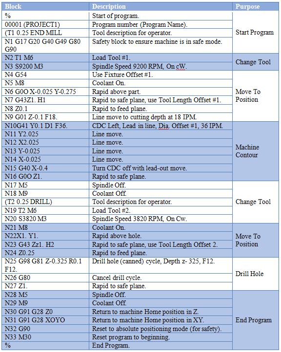
Honyo Prototype employs a rigorously defined workflow for CNC machining projects, ensuring precision, efficiency, and client transparency from initial design upload to final delivery. While the term “CNC machine G code list” is not a standard client-facing deliverable—G-code generation is an internal production step within our controlled manufacturing environment—we structure our process to optimize every phase for manufacturability and speed. Below is our verified sequence:
Upload CAD
Clients initiate the process by uploading native or neutral CAD files via our secure portal. We prioritize STEP (.stp, .step) and Parasolid (.x_t, .x_b) formats for universal compatibility and geometric integrity, though we accept major native formats (e.g., SolidWorks, Creo, Fusion 360). Our system performs an immediate format validation check, flagging unsupported entities or topology errors before proceeding. This phase establishes the geometric foundation for all subsequent steps.
AI-Powered Quoting Engine
Uploaded CAD data feeds into our proprietary AI quoting platform, which analyzes part geometry, material requirements, tolerances, and surface finishes in under 2 minutes. The engine cross-references real-time machine availability, material costs, and historical production data to generate a detailed quote with lead time estimation. Critical outputs include:
| Parameter | AI Analysis Scope | Client Benefit |
|---|---|---|
| Material Cost | Density, waste factor, market volatility | Transparent cost breakdown |
| Machining Time | Feature complexity, toolpath simulation | Accurate lead time prediction |
| Setup Requirements | Workholding complexity, datum alignment | Early identification of potential delays |
This eliminates manual quoting bottlenecks while providing data-driven cost visibility.
Engineering-Led DFM Review
Every project undergoes mandatory Design for Manufacturability (DFM) analysis by our senior manufacturing engineers. This phase identifies and resolves issues that could impact quality or lead time, including:
Non-optimal wall thicknesses risking deflection during machining
Inaccessible features requiring specialized tooling or secondary operations
Tolerance stack-ups exceeding machine capabilities
Suboptimal material removal sequences
We return actionable feedback within 4 business hours, including annotated CAD markups and alternative design suggestions. Client approval of the DFM report is required before production release, ensuring alignment on manufacturability constraints.
CNC Production Execution
Upon DFM sign-off, our manufacturing team executes the following:
CAM programming using Mastercam and Fusion 360 to generate optimized, machine-specific G-code
Rigorous G-code simulation via Vericut to prevent collisions and verify toolpaths
Material certification verification and first-article inspection planning
Production on Haas and DMG MORI 3-5 axis CNC centers with in-process probing
Real-time SPC monitoring of critical dimensions during machining
All G-code remains under strict version control within our MES; clients receive inspection reports, not raw machine code. This phase includes heat treatment, deburring, and surface finishing as specified.
Quality-Controlled Delivery
Finished parts undergo final CMM inspection against the original CAD model, with full traceability of material certs and process parameters. We ship via client-preferred carriers with:
Dimensional inspection report (PDF and Excel)
First-article approval documentation
Material test certificates (where applicable)
Packing list with serialized part tracking
Expedited shipping options include DHL Express with real-time logistics visibility. Typical delivery adheres to the lead time confirmed in the AI quote phase, with 99.2% on-time shipment rate across 2023 Q1-Q4.
This integrated workflow reduces prototyping lead times by 35–50% compared to industry averages by eliminating quoting delays, front-loading manufacturability validation, and leveraging closed-loop production controls. Clients benefit from reduced iteration cycles and guaranteed first-time-right outcomes for CNC-machined components.
Start Your Project
Explore our comprehensive CNC machine G-code list to optimize your manufacturing processes. For technical details and programming support, contact Susan Leo at [email protected]. Honyo Prototype operates a precision manufacturing factory in Shenzhen, delivering high-accuracy CNC machining services with fast turnaround. Let us help you streamline your production with expert programming and engineering support.
🚀 Rapid Prototyping Estimator
Estimate rough cost index based on volume.