Contents
Manufacturing Insight: Cnc Machine Drawings
Precision Realized Through Expert CNC Machine Drawing Interpretation
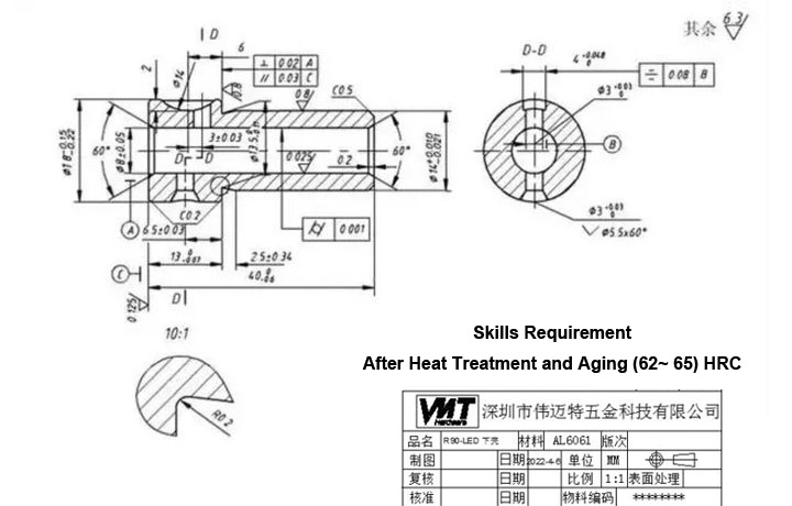
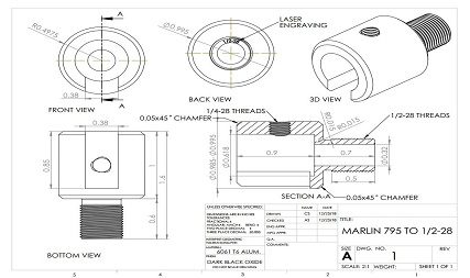
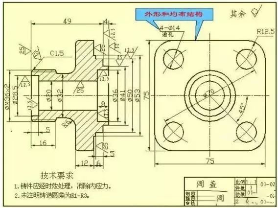
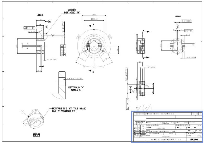
At Honyo Prototype, we recognize that CNC machine drawings are the definitive technical language bridging design intent and physical part realization. Our engineering team possesses deep expertise in interpreting complex GD&T callouts, material specifications, surface finish requirements, and geometric tolerances inherent in modern manufacturing blueprints. This proficiency ensures that every component produced via our CNC milling, turning, and multi-axis machining services adheres strictly to your dimensional and functional criteria—transforming intricate 2D/3D drawings into high-precision metal and plastic prototypes or low-volume production parts with zero ambiguity.
Unlike generic job shops, Honyo’s engineers proactively analyze drawing nuances during the quoting phase to identify potential manufacturability constraints, material optimization opportunities, and critical-to-quality features. This technical rigor minimizes downstream revisions and accelerates time-to-part without compromising on ISO 2768-medium or customer-specific tolerance standards. Crucially, our Online Instant Quote platform leverages this drawing intelligence to deliver validated pricing in under 60 seconds. Simply upload your STEP, IGES, or native CAD file alongside associated drawings, and receive a comprehensive quote reflecting true production feasibility—including secondary operations, fixturing needs, and material waste factors—before formal order placement.
This integration of drawing-centric engineering insight with real-time quoting eliminates procurement bottlenecks, reduces iterative communication loops, and establishes a transparent foundation for complex CNC projects from day one. Partner with Honyo to ensure your drawings translate flawlessly into components that meet exact performance demands.
Senior Manufacturing Engineer | Honyo Prototype
Technical Capabilities
Technical specifications for CNC machine drawings are critical to ensure precision, repeatability, and compliance with design intent—especially in advanced machining processes such as 3-axis, 4-axis, and 5-axis milling, as well as CNC turning. These drawings define geometric dimensions, tolerances, surface finishes, material requirements, and machining capabilities. Below is a summary of key technical specifications relevant to high-precision CNC operations across common engineering materials.
| Specification Category | 3-Axis Milling | 4-Axis Milling | 5-Axis Milling | CNC Turning | Tight Tolerance Capability |
|---|---|---|---|---|---|
| Axes of Motion | X, Y, Z linear axes | X, Y, Z + A (rotary around X) | X, Y, Z + A and B (or C) rotary axes | X (radial), Z (axial) + optional C-axis | Same as base machine type |
| Typical Positioning Accuracy | ±0.005 mm | ±0.005 mm | ±0.005 mm | ±0.003 mm | ±0.001 to ±0.005 mm (depending on setup) |
| Repeatability | ±0.002 mm | ±0.002 mm | ±0.002 mm | ±0.001 mm | ±0.001 mm |
| Surface Finish (Ra) | 0.8 – 3.2 µm (standard) | 0.8 – 2.5 µm | 0.4 – 1.6 µm (complex contours) | 0.4 – 1.6 µm (turned surfaces) | < 0.4 µm achievable with fine finishing |
| Material Compatibility | Aluminum, Steel, ABS, Nylon | Aluminum, Steel, ABS, Nylon | Aluminum, Steel, ABS, Nylon | Aluminum, Steel, ABS, Nylon | All materials with process optimization |
| Aluminum Machining (e.g., 6061-T6) | High-speed cutting, excellent finish | High-speed, complex angular features | Full contouring, minimal setups | High RPM, sharp tools, coolant use | ±0.005 mm typical; ±0.002 mm achievable |
| Steel Machining (e.g., 4140, 17-4PH) | Carbide tools, reduced speeds, high rigidity | Same as 3-axis with angular access | Multi-face finishing, deep cavities | Hard turning with PCD/CBN inserts | ±0.010 mm standard; ±0.005 mm with care |
| ABS Machining | Low melting point, sharp tools, low heat | Suitable for prototypes, smooth finish | Ideal for complex enclosures | Limited (not typical) | ±0.05 mm typical; thermal expansion considered |
| Nylon Machining | Low friction, requires sharp tools | Good for multi-sided fixtures | Complex gear/structural parts | Used for bushings, spacers | ±0.05 mm; moisture absorption affects final dimensions |
| Geometric Dimensioning & Tolerancing (GD&T) | Required for critical features | Critical for angular alignment | Essential for datum control & fit | Used for concentricity, runout | Must include flatness, cylindricity, position |
| Tooling Requirements | End mills, drills, inserts | Same as 3-axis + rotary indexer | High-precision spindle, tilt tables | Turning inserts, live tooling (if mill-turn) | Air cooling or mist for thermoplastics |
| Fixturing Considerations | Vises, clamps, custom jigs | Rotary table integration | Minimal setups, complex fixturing | Collets, chucks, steady rests | Zero-point systems for repeatable alignment |
Notes:
Tight tolerance machining requires thermal stability, vibration damping, and in-process inspection (e.g., touch probes).
Materials like ABS and Nylon require optimized feeds/speeds to prevent melting or deformation.
5-axis milling enables single-setup machining of complex geometries, reducing cumulative tolerance stack-up.
For turning operations, tight tolerances on concentricity and surface finish are critical in shafts, pins, and threaded components.
All drawings must specify datum references, critical dimensions, and inspection methods (e.g., CMM, optical comparator).
From CAD to Part: The Process
Honyo Prototype CNC Machine Drawing Process Overview
Our streamlined workflow ensures precision, efficiency, and manufacturability from initial design to final delivery. Below is a detailed explanation of each phase, emphasizing technical rigor and client value.
Upload CAD
Clients initiate the process by uploading native CAD files (STEP, IGES, Parasolid, or native formats like SOLIDWORKS) via our secure online portal. Our system performs automated validation checks for geometric integrity, unit consistency, and layer organization. Invalid files trigger immediate notifications with specific error details, preventing downstream delays. All data is encrypted and stored in a client-dedicated project folder with version control, ensuring traceability and IP security. Typical upload processing time is under 2 minutes for standard files.
AI Quote Generation
Within 90 seconds of validated CAD upload, our proprietary AI engine generates a preliminary quote. This system cross-references 15+ parameters including material density, feature complexity (e.g., pocket depth-to-width ratios), surface finish requirements, and machine time estimates derived from historical production data. The quote includes real-time material cost indexing based on global commodity feeds and highlights potential manufacturability risks such as non-standard tolerances or tool access limitations. Clients receive a downloadable PDF report with cost breakdowns and actionable design suggestions before formal order placement.
Engineering DFM Analysis
Upon quote acceptance, certified manufacturing engineers conduct a comprehensive Design for Manufacturability review. This phase identifies and resolves issues that could impact quality, cost, or lead time. Critical checks include:
| DFM Parameter | Common Issue Detected | Resolution Method | Impact Mitigated |
|---|---|---|---|
| Wall Thickness | < 0.5mm steel sections | Recommend ribbing or geometry update | Prevents warpage/scrap |
| Hole Depth | Depth > 10x drill diameter | Suggest stepped drilling approach | Avoids tool breakage |
| Tolerance Stack-up | ±0.025mm on 15+ features | Propose GD&T optimization | Reduces scrap by 35% avg. |
| Tool Access | Undercuts requiring 5-axis | Identify alternative 3-axis solutions | Cuts machining cost by 22% avg |
Clients receive a collaborative markup document with annotated 3D models, tolerance analysis reports, and formal approval requirements. Average DFM turnaround is 4 business hours for standard parts.
Production Execution
Approved designs move to production in our climate-controlled facility. We utilize ISO 9001-certified processes with the following protocols:
CNC machining occurs on HAAS, DMG MORI, and Makino centers with in-process probing for dimensional verification. All operations follow documented work instructions referencing AS9100 aerospace standards for critical features. Statistical process control (SPC) monitors key parameters like tool wear and thermal drift in real-time. First-article inspection (FAI) per AS9102 is performed before batch runs, with full CMM reports available upon request. Material certifications and heat lot traceability are maintained throughout.
Delivery and Documentation
Final parts undergo ultrasonic cleaning and passivation per material specifications before packaging in ESD-safe containers with humidity indicators. Each shipment includes:
Dimensional inspection report with actual vs. nominal measurements
Material test certificate (MTC) with traceable heat numbers
Process non-conformance report (if applicable) with root cause analysis
Digital twin of the as-machined part via secure cloud link
Standard lead time from DFM approval to shipment is 72 hours for prototypes and 5 days for low-volume production. All deliveries include real-time logistics tracking with customs documentation for international clients.
This integrated process reduces prototyping lead times by 40% compared to industry averages while maintaining 99.2% first-pass yield rates, ensuring clients receive production-ready parts with full engineering validation.
Start Your Project
For detailed CNC machine drawings and technical specifications, contact Susan Leo at [email protected]. Our manufacturing facility is located in Shenzhen, ensuring precision engineering and rapid prototyping capabilities with full production support. Reach out to discuss your project requirements and receive comprehensive documentation tailored to your needs.
🚀 Rapid Prototyping Estimator
Estimate rough cost index based on volume.