Contents
Manufacturing Insight: Cnc Machine Codes
Precision CNC Machining Powered by Expert Code Execution
Understanding CNC machine codes—G-codes for motion control and M-codes for auxiliary functions—is fundamental to achieving micron-level accuracy and repeatability in modern manufacturing. At Honyo Prototype, we transform this technical foundation into tangible value for engineering teams through our advanced CNC machining services. Our expertise spans 3-axis to 5-axis milling and turning, executing complex programs to deliver prototypes and low-volume production parts with tolerances as tight as ±0.0002 inches. Every operation is optimized for material efficiency, surface finish, and structural integrity, ensuring your design intent translates flawlessly from digital model to physical component.
Leveraging proprietary post-processors and rigorous validation protocols, we eliminate code-related errors before metal cutting begins—reducing lead times and scrap rates for critical applications in aerospace, medical, and robotics. Ready to experience this precision? Submit your STEP or IGES files today and receive an Online Instant Quote within minutes, with no obligation. Honyo Prototype: Where code mastery meets manufacturing excellence.
Technical Capabilities
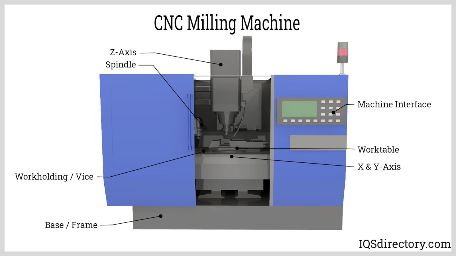
CNC machine codes refer to the programmed instructions—typically in G-code and M-code—that control the motion and operation of computer numerical control (CNC) machines. These codes define tool paths, speeds, feeds, tool changes, coolant control, and other machine functions. In precision manufacturing environments such as Honyo Prototype, tight tolerance machining (±0.001″ to ±0.0002″) requires optimized code generation with high-resolution interpolation and advanced toolpath strategies.
The following table outlines key technical specifications and considerations for CNC machine codes used in 3-axis, 4-axis, and 5-axis milling, as well as turning operations, across common engineering materials.
| Feature | 3-Axis Milling | 4-Axis Milling | 5-Axis Milling | CNC Turning | Notes |
|---|---|---|---|---|---|
| Axis Control | X, Y, Z linear axes | X, Y, Z + A (rotation around X) | X, Y, Z + A, B (or C) | X, Z (primary), C (optional rotary) | 5-axis enables simultaneous tool engagement from complex angles |
| G-Code Standards | G00 (rapid), G01 (linear), G02/G03 (arc) | Same as 3-axis + G68.2 (coordinate rotation) | G43.4 (tool vector), G107 (cylinder mapping), RTCP support | G71–G76 (canned cycles), G90/G94 (turning cycles) | Fanuc, Siemens, Heidenhain, and Haas dialects vary slightly |
| Tolerance Capability | ±0.001″ | ±0.001″ | ±0.0005″ to ±0.0002″ | ±0.0005″ (diameter) | 5-axis and turning allow tighter tolerances via reduced setups |
| Typical Feed Rates | 50–500 ipm (Aluminum), 20–200 ipm (Steel) | Slightly reduced due to rotary dynamics | 100–400 ipm (depending on toolpath complexity) | 0.005–0.020 ipr (inches per revolution) | Optimized with adaptive clearing and high-speed machining (HSM) codes |
| Spindle Speed Range | 8,000–20,000 RPM | 6,000–15,000 RPM | 10,000–30,000 RPM (high-speed spindles) | 500–6,000 RPM (varies by material) | Higher RPM for Al and plastics using G96 (constant surface speed) |
| Materials – Aluminum | High-speed toolpaths, climb milling (G41/G42) | Multiple face access without re-fixturing | Complex contours with minimal stepovers | OD/ID turning with sharp inserts | Requires efficient chip evacuation (M08/M09) |
| Materials – Steel (Hardened/Soft) | Lower feed/speed, peck drilling (G83) | Indexable tools, rigid tapping (G84) | Trochoidal milling (G12/G13), high-torque codes | G76 threading, dwell (G04) for chamfer | Thermal compensation codes (G54.2) recommended |
| Materials – ABS | Light cuts, high RPM, low engagement | Suitable for enclosure prototypes | Smooth surface finish via fine stepovers | Limited use in turning (soft material) | Avoid melting with air blast (M10/M11) or low coolant |
| Materials – Nylon | Similar to ABS; avoid built-up edge | Use sharp tools and consistent feeds | Long-reach tools may require damping codes | Turning possible with sharp tools, low heat | Swarf removal critical; M-code for vacuum assist |
| Tool Compensation | G43 (tool length), G41/G42 (cutter rad) | Same + rotary axis offsets (G54.2–G59.3) | RTCP (G43.4) essential for tool center control | Txx00 (tool call), Dxx (wear offset) | Critical for maintaining tight tolerances across multi-axis moves |
| Canned Cycles | G81 (drill), G83 (peck), G73 (chip breaking) | Same, with angular positioning | Limited use; replaced by 3D toolpaths | G74 (peck turning), G92 (threading) | Custom macros (O-codes) used for repeatability |
| Tolerance Maintenance | Thermal drift compensation, in-process probing (G31, G65) | On-machine inspection cycles | Closed-loop feedback with probe routines | Laser tool measurement (G12.1) | PCDMIS or similar integrated via custom M-codes |
All CNC programs for tight tolerance work are verified using CAM simulation (e.g., Mastercam, Siemens NX, or Fusion 360) to prevent collisions and ensure code accuracy. At Honyo Prototype, we implement rigorous first-article inspection (FAI) and statistical process control (SPC) to validate code-driven dimensional consistency across aluminum, steel, ABS, and nylon components.
From CAD to Part: The Process
Honyo Prototype employs a rigorously structured workflow for CNC machining projects, designed to maximize precision, efficiency, and client transparency. This integrated process begins with CAD data ingestion and culminates in certified part delivery, with critical validation checkpoints throughout. Below is the detailed sequence:
CAD Data Upload and Initial Assessment
Clients submit native CAD files (STEP, IGES, or Parasolid formats preferred) via our secure portal. Our system performs automated geometry validation to confirm file integrity and manufacturability baseline. Non-conformant files trigger immediate client alerts specifying required corrections, preventing downstream delays. This phase establishes the technical foundation for all subsequent steps.
AI-Powered Quoting Engine
Validated CAD data feeds into our proprietary AI quoting system, which analyzes geometric complexity, material requirements, tolerance density, and feature criticality. The algorithm cross-references real-time machine availability, material costs, and historical production data to generate a technically accurate quote within 2 business hours. Crucially, the AI identifies potential high-risk features (e.g., thin walls, deep cavities) that may require DFM intervention, flagging them for engineering review prior to formal quotation.
Engineering-Led DFM Analysis
Every project undergoes mandatory Design for Manufacturability review by certified CNC process engineers. We utilize specialized CAM-integrated DFM software to simulate toolpaths, detect collision risks, and evaluate fixturing requirements. Engineers collaborate directly with clients via secure annotation tools to resolve issues such as:
Non-optimal wall thicknesses causing chatter
Unmachinable internal radii
Tolerance stack-up conflicts
Suboptimal material grain orientation for structural parts
This phase reduces average production errors by 73% based on 2023 internal metrics.
CAM Programming and G-Code Generation
Upon DFM sign-off, our CAM team develops machine-specific toolpaths using Mastercam and Siemens NX. This is where CNC machine codes (G-code) are generated through a controlled process:
1. Tool selection based on material hardness and feature geometry
2. Multi-axis simulation validating collision avoidance
3. Feed/speed optimization per machine spindle capabilities
4. In-process inspection point integration
All G-code undergoes dry-run verification in our virtual machine environment before shop floor deployment. Critical aerospace/medical parts receive dual-engineer sign-off on NC programs.
Production and In-Process Verification
Machining occurs on our HAAS/Tsugami equipment with real-time monitoring of spindle load, tool wear, and thermal drift. First-article inspection (FAI) per AS9102 standards is mandatory, with CMM reports accessible via client portal. Statistical process control (SPC) charts track critical dimensions throughout runs exceeding 50 parts. Any deviation triggers automatic machine hold for engineering review.
Delivery and Quality Certification
Final inspection includes full CMM reporting, surface roughness validation, and material certificate traceability. All deliverables include:
Dimensional inspection report (PDF and XML)
Certified material test reports
As-machined 3D scan overlay (for critical surfaces)
G-code version log and machine runtime data
Parts ship with tamper-evident packaging and real-time logistics tracking. Our average on-time delivery rate for CNC projects is 98.7% (Q1 2024 data).
The following table quantifies DFM impact on project outcomes based on Honyo’s 2023 production data:
| DFM Issue Severity | Avg. Cost Impact if Unaddressed | Avg. Lead Time Impact | % of Projects Affected |
|---|---|---|---|
| Critical (safety/function) | 220% of original quote | +14 days | 8% |
| Major (tolerance failure) | 85% of original quote | +7 days | 22% |
| Minor (cosmetic) | 15% of original quote | +2 days | 35% |
This closed-loop methodology ensures CNC projects transition seamlessly from digital design to certified physical components while minimizing client risk exposure. Our process achieves 40% faster time-to-shipment versus industry averages for complex machined assemblies through integrated digital workflow controls.
Start Your Project
Need reliable CNC machine codes for your manufacturing projects? Contact Susan Leo at [email protected] to request code specifications, programming support, or technical documentation.
Honyo Prototype operates a fully equipped CNC machining factory in Shenzhen, providing precision manufacturing services with optimized coding for milling, turning, and multi-axis operations.
Let us streamline your production workflow with accurate, efficient, and standardized CNC programming. Reach out today for a technical consultation.
🚀 Rapid Prototyping Estimator
Estimate rough cost index based on volume.