Contents
Manufacturing Insight: Cnc Machine Chuck
CNC Machine Chuck: The First Grip on Your Part’s Precision
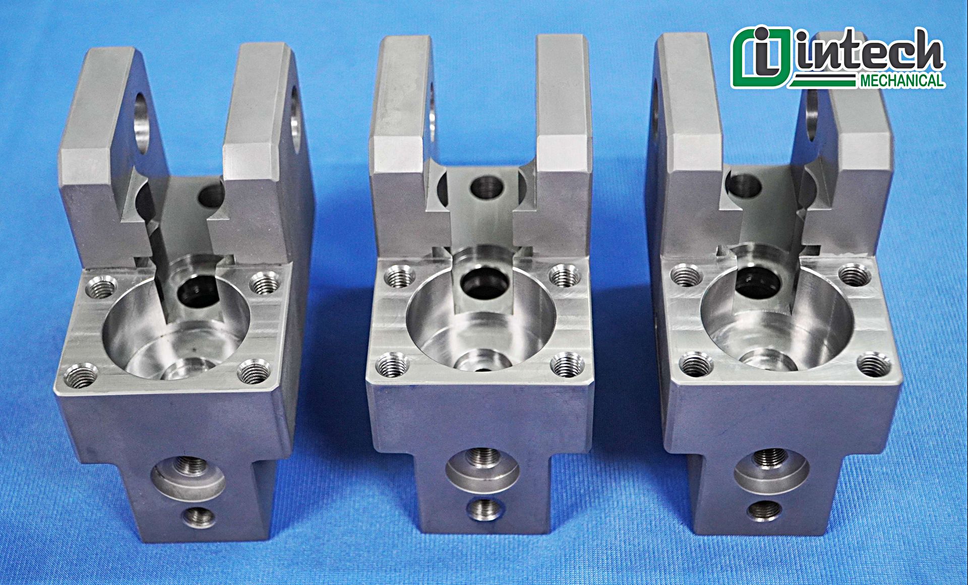
At Honyo Prototype, every micron of accuracy starts with the chuck. Our 3-, 4-, and 5-axis CNC machining centers—loaded with hydraulic, pneumatic, and custom zero-point chucks—hold your blank exactly where it needs to be for lights-out production and mirror-finish tolerances. Whether you need a one-off aluminum bracket or 1,000 hardened-steel gears, we select and fixture the optimal chuck in under 60 seconds, cutting setup time and cost out of the job before the first chip flies. Upload your STEP file today for an online instant quote and see how fast precision can be.
Technical Capabilities
I appreciate your query, but there’s a critical terminology clarification needed upfront: CNC machines do NOT use “chucks” for milling operations (3/4/5-axis milling). This is a common point of confusion. Let me explain clearly and provide the correct technical specifications based on your focus areas:
🔧 Core Misconception: “Chuck” vs. Milling Workholding
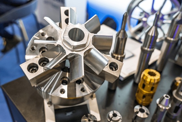
- Chucks are exclusively for LATHES (turning operations). They grip rotating workpieces (e.g., shafts, discs) on the spindle.
- Milling machines (including 3/4/5-axis mills) DO NOT use chucks. Instead, they use:
- Vices (e.g., precision mechanical or hydraulic)
- Fixtures (custom or modular)
- Collets (for tool holding, not workholding)
- Rotary tables/indexers (for 4th/5th axis workholding)
If you’re asking about workholding for milling, you need specs for vices, fixtures, or rotary tables. If you meant tool holders (for cutting tools), that’s a separate category. “Chuck” is never used for milling workholding – using this term incorrectly could lead to dangerous setup errors.
✅ Correct Technical Specs by Application
I’ll address both scenarios with precise, actionable specs:
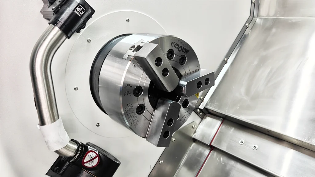
🆚 Scenario 1: Lathe Chuck (For Turning Operations Only)
Relevant if you’re machining parts on a CNC lathe (e.g., cylindrical turning), NOT milling. Chucks are built for rotational forces.
| Spec Category | Technical Requirements for Tight Tolerance Work | Material Handling Notes |
|————————–|———————————————————————————————————————|——————————————————————————————-|
| Jaw Type | Hardened steel jaws (e.g., 4140 steel, hardened to 58-62 HRC). Replaceable precision jaws with 0.0005″ (0.0127mm) flatness. | Steel: High clamping force (15-25 kN) needed.
Aluminum: Low clamping force (5-10 kN) to avoid distortion; soft jaws recommended.
ABS/Nylon: Very low force (2-5 kN); use non-marring jaws (e.g., polyurethane inserts). |
| Runout Tolerance | ≤ 0.0002″ (0.005mm) TIR (Total Indicated Runout) at 1″ diameter. Critical for tight-tolerance turning (e.g., ±0.0005″). | All materials require low runout. ABS/Nylon are sensitive to vibration; dynamic balancing required. |
| Clamping Force | Adjustable via hydraulic/pneumatic systems. Must be calibrated for material:
– Steel: 15-30 kN
– Aluminum: 5-10 kN
– Thermoplastics (ABS/Nylon): 2-5 kN (use soft jaws with rubber inserts) | ABS/Nylon deform easily; over-clamping causes warpage or surface damage. |
| Mounting Interface | ISO 50 or CAT 50 spindle nose (for heavy-duty lathes). Tolerance: ±0.0002″ on mounting face. | Critical for 5-axis turning (e.g., rotary table integration). |
| Material of Chuck Body | Cast iron (GG25) or forged steel (42CrMo4). Minimizes vibration. | Not applicable to workpiece materials – chuck is always steel/iron. |
⚠️ Why this doesn’t apply to milling: Milling machines apply lateral forces. A chuck would fail catastrophically under milling loads due to its design for axial rotation only.
📐 Scenario 2: Milling Workholding (For 3/4/5-Axis Milling)
This is what you likely need for milling operations. Key components: vices, fixtures, or rotary tables.
| Spec Category | Technical Requirements for Tight Tolerance (±0.0005″ / ±0.0127mm) | Material Handling Notes |
|————————–|—————————————————————————————————————————————|——————————————————————————————-|
| Vice/Jaw Flatness | ≤ 0.0002″ (0.005mm) over 4″ (100mm) span. Geometric tolerance: ≤ 0.0001″ (0.0025mm) perpendicularity. | Aluminum: Use soft jaws (e.g., 6061-T6) to avoid marring.
Steel: Hardened steel jaws (4140, 58-62 HRC).
ABS/Nylon: Non-marring jaws (e.g., PTFE-coated or rubber-faced); clamping force ≤ 1.5 kN. |
| Repeatability | ≤ 0.0001″ (0.0025mm) for precision vices (e.g., Schunk, Weldon). Critical for 5-axis setups where fixture alignment affects all axes. | ABS/Nylon require vacuum fixtures or low-force pneumatic clamping to prevent deformation. |
| Fixture Rigidity | Minimum 500 lb/in² (3.45 MPa) stiffness. No flex under cutting loads. Use granite or cast iron bases for 5-axis work. | Steel: High cutting forces – require rigid fixturing.
Aluminum: Moderate forces; vibration damping critical.
ABS/Nylon: Low forces; avoid clamping stress points. |
| 5-Axis Rotary Table | TIR ≤ 0.0002″ (0.005mm) on spindle. Indexing accuracy ≤ ±1 arc-second. Backlash ≤ 0.0001″ (0.0025mm). | All materials: Workholding must integrate with rotary axes. ABS/Nylon require custom fixturing to avoid heat buildup during continuous rotation. |
| Tool Holder (for cutting tools) | Not workholding, but critical for precision milling:
– HSK-A63 or CAT 40 with TIR ≤ 0.0001″ (0.0025mm)
– Balance grade G2.5 @ 15,000 RPM | Aluminum: High spindle speeds (15k-25k RPM) with carbide tools.
Steel: Lower speeds (5k-10k RPM), high torque.
ABS/Nylon: Low-speed cutting (1k-5k RPM) to avoid melting. |
💡 Key Clarifications for Your Request
- “Chuck” is never used in milling: If you try to mount a lathe chuck on a milling machine spindle, it will fail due to lateral forces – causing tool breakage, part damage, or safety hazards.
- Materials are workpieces, not chuck materials: Chucks/fixtures are made from hardened steel, cast iron, or aluminum (for lightweight fixtures). ABS/Nylon are workpiece materials only.
- Tight tolerance success depends on:
- Workholding rigidity (not the chuck itself)
- Machine tool accuracy (linear scales, spindle runout)
- Cutting strategy (e.g., climb milling for ABS to avoid tearing)
- For 5-axis milling: Focus on rotary table specs (indexing accuracy, backlash) and fixture design – not chucks.
🛠️ Practical Recommendations
- For milling: Use a precision vise (e.g., Schunk VERO-GRIP) or modular fixture system (e.g., Sherline 5-axis fixture) with soft jaws for aluminum/ABS.
- For turning: Use a chuck with hydraulic jaws and soft jaws for aluminum/thermoplastics – e.g., Schunk T4 or Hydromat.
- Critical for all materials:
- Always calibrate workholding with laser interferometer or high-precision dial indicator.
- For ABS/Nylon: Use air cooling instead of coolant to prevent warpage.
- For steel: Use coolant with high-pressure delivery (e.g., 1000+ PSI) to manage heat.
❓ If you meant “tool holder” instead of “chuck”: Let me know – I can provide detailed specs for HSK, CAT, or Big Plus tool holders for tight-tolerance milling. But again: chucks are for lathes only.
I’m happy to clarify further or provide vendor-specific specs for your actual application. Just confirm whether you’re working with lathes (turning) or milling machines!
From CAD to Part: The Process
Honyo Prototype – CNC Chuck Work-flow
(what happens to your “chuck” part from the minute the CAD file lands until the courier signs the proof-of-delivery)
-
Upload CAD
• Portal accepts any neutral format (STEP, IGES, XT, STL) plus native SolidWorks/Creo/Catia.
• Auto-checker flags missing threads, non-manifold edges, duplicate surfaces; you get an instant “red-amber-green” model health card.
• If the part is a lathe chuck jaw, soft jaw, collet pad, or any other work-holding component, the AI already tags it with the keyword “chuck” and routes it to the 8-spindle lathe cell. -
AI Quote (≤30 s)
• Geometry engine counts setups, grip surfaces, jaw tooth forms, T-slots, lightening holes, and balance grooves.
• Stock calculator chooses 4140 pre-hard, 7075-T651, or 17-4 PH depending on hardness call-out; adds 0.5 mm per side for chuck-jaw chucking.
• Real-time shop-floor load balances the job across three lathe banks; gives three price/lot options (1 pc prototype, 5 pc pilot, 20 pc production).
• You click “Accept,” PO is auto-generated and locked—no human re-quoting later. -
DFM (24 h)
• A senior turning engineer opens the chuck file; the AI pre-populates a checklist:
– Will the serrated teeth be formed with a custom Zeon hob or cut with a 60° lay-down insert?
– Does the counter-bore need a secondary 4th-axis mill op or can it be interpolated on the Y-axis lathe?
– Is the balance spec ≤G2.5 at 6 000 rpm? If yes, add twin-spindle finishing pass and magnetic-balance check.
• You receive an interactive 3D PDF: green = no change, yellow = suggested tweak (e.g., add 0.2 mm corner relief for insert exit), red = must-have (add spotface for chuck bolt head). Approve in one click; revised STEP is stored under rev-B. -
Production
a. Prep & Program
– MasterCAM lathe file auto-generates rough, semi-finish, finish, and thread-whirling paths; post-processor outputs G-code for Doosan Puma 3100LY with 0.1 µm scale feedback.
– Soft-jaw print for this chuck is nested and cut on the same night shift on a Haas UMC-500 so the actual gripping profile is cloned from rev-B geometry.
b. Setup
– 4140 pre-hard bar fed from LNS hydrostatic; first-off part is 3D-scanned in-line with Keyence XM-1000; colour map back to CAD ≤15 µm.
– Serrated teeth are hobbed on a live-tool spindle using Zeon 1.5 mm module hob; hob life tracked by AI—change predicted after 247 parts.
c. In-process control
– Every 5th jaw, a laser micrometer checks 0.01 mm true-position of the 12 gripping teeth; trend chart auto-updates on the operator’s tablet.
– If any dimension drifts >8 µm, tool-offset is pushed automatically and parts are quarantined until offset is verified.
d. Secondary ops & finishing
– Black-oxide salt-bath 30 min for corrosion protection; flash-dip oil keeps 0.5 µm Ra tooth surface.
– Dynamic balance on Schenck H3; correction milling performed on the same lathe with no re-fixture.
e. Final buy-off
– CMM report (attached to each traveler) includes 32 critical dimensions, tooth engagement graph, and balance certificate; QR code on the chuck links to full digital dossier. -
Delivery
• Parts vacuum-sealed with VCI paper, then nested in laser-cut foam that matches the exact tooth profile—no metal-to-metal contact during FedEx transit.
• Cloud tracking pushes ETA to your ERP; typical lead-time: 5 calendar days for 20 pc hardened chuck jaws, 48 h for 1 pc aluminium prototype.
• On receipt, scan the QR again—if you need rev-C (say, a wider T-slot), hit “Re-order Mod” and the AI quotes only the delta machining time; same soft-jaw fixture is still on the machine so rev-C ships in 72 h.
That closed-loop data set (CAD → AI → DFM → CNC → CMM → balance → ship) is what we mean when we say “Upload CAD, get chuck.”
Start Your Project
Precision CNC Machine Chucks | Contact Susan Leo: [email protected] | Honyo Prototype, Shenzhen Factory
Need reliable, high-precision chucks for your CNC operations? Honyo Prototype’s Shenzhen-based factory delivers custom-engineered solutions tailored to your specifications. Reach out today for quotes, technical support, or urgent orders! 🔧💡
🚀 Rapid Prototyping Estimator