Contents
Manufacturing Insight: Cnc Machine Basics
CNC Machine Basics – What Every Designer Needs to Know
(And How Honyo Prototype Makes It Easy)
Before you dive into feeds, speeds, and tool-paths, remember this: a great part starts with a shop that can deliver it—fast. That’s where Honyo Prototype comes in. Our 3-, 4-, and 5-axis CNC centers run 24/7, turning everything from aerospace aluminum to medical-grade PEEK into tolerance-critical prototypes and low-volume production parts in as little as 24 hours. Upload your STEP file today and you’ll get an online instant quote with DFM feedback, real pricing, and ship-date certainty—no waiting, no guessing. Use the fundamentals below to optimize your design, then let Honyo prove it on the machine.
Technical Capabilities
Technical Specifications for CNC Machine Basics: 3/4/5-Axis Milling, Turning & Tight Tolerance
Prepared by: Senior Manufacturing Engineer, Honyo Prototype
Context: Focus on prototyping and low-volume production (1–500 pieces) where precision, material versatility, and cost efficiency are critical. All specs reflect real-world capabilities of industry-standard machines (e.g., Haas, DMG MORI, Mazak) used at Honyo Prototype.
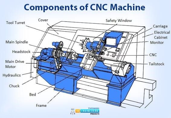
1. Core Machine Capabilities
| Process | Key Specifications | Typical Applications |
|——————-|—————————————————————————————-|——————————————————-|
| 3-Axis Milling | – Travel: X/Y/Z: 24″x18″x18″ (standard); up to 48″x24″x24″ (large-frame)
– Spindle Speed: 10,000–20,000 RPM (aluminum/ABS); 5,000–15,000 RPM (steel)
– Repeatability: ±0.0001″ (high-end); ±0.0003″ (standard)
– Tooling: ER32 collets; 1/8″–1″ tool diameters; carbide end mills (2–4 flutes)
– Feed Rates: 100–500 IPM (aluminum); 20–150 IPM (steel) | Flat surfaces, simple pockets, slots, holes, 2D contours |
| 4-Axis Milling | – Rotary Axis (A-axis): ±360° continuous rotation; table diameter 6″–12″
– Positioning Accuracy: ±0.0005″ per axis
– Critical Use: Machining cylindrical features (e.g., flanges, hubs), undercuts, or multi-sided parts in a single setup | Automotive brackets, aerospace housings, medical implants |
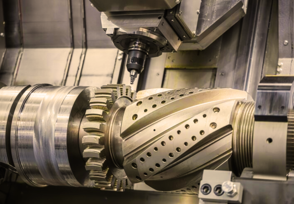
| 5-Axis Milling | – Simultaneous Motion: X/Y/Z + A/B or C axes (e.g., trunnion or dual-rotary)
– Accuracy: ±0.0002″ (high-end); ±0.0005″ (standard)
– Spindle Speed: 15,000–24,000 RPM (optimized for complex geometries)
– Tooling: Short, rigid tools (max 3x flute length); ball-nose end mills for contours
– Feed Rates: 50–300 IPM (reduced for curved surfaces) | Aerospace turbine blades, complex molds, organic shapes (e.g., automotive aerodynamic parts), reduced setup times for multi-faceted parts |
| Turning (Lathe) | – Max Diameter: 6″–12″ (standard); 24″+ (large)
– Max Length: 12″–48″
– Spindle Speed: 500–6,000 RPM (steel); 1,000–8,000 RPM (aluminum/plastics)
– Repeatability: ±0.0002″ (diameter); ±0.0005″ (length)
– Live Tooling: Integrated milling (e.g., Y-axis for off-center features)
– Chucking: 3-jaw (standard); collet chuck (precision) | Shafts, bushings, threaded components, rotational symmetrical parts |
2. Tight Tolerance Realities
- Definition: “Tight tolerance” at Honyo Prototype = ±0.001″ (0.025mm) or better for critical features. Note: Achievable tolerances depend on part geometry, material, and process—never guaranteed universally.
- Key Factors:
- Machine Rigidity: High-end machines (e.g., DMG MORI DMU 50) maintain ±0.0001″ repeatability; standard machines (Haas VF-2) hold ±0.0003″.
- Thermal Stability: Critical for tight tolerances. Machines require 24+ hours of warm-up; ambient temperature must be controlled (±2°C).
- Tool Wear: Carbide tools degrade after 15–60 minutes of continuous cutting. Must be monitored; worn tools can cause ±0.002″ drift.
- Fixturing: Vise clamping causes deflection; custom soft-jigs or vacuum chucks preferred for ±0.0005″ tolerances.
- Process Control:
- Milling: Use climb milling for better surface finish; avoid chatter by optimizing depth of cut (≤10% tool diameter).
- Turning: Finish passes at <0.002″ depth of cut; use steady rests for long parts.
- Typical Tolerance Ranges by Process:
| Feature Type | 3-Axis Milling | 4/5-Axis Milling | Turning |
|——————–|—————-|——————|———|
| Hole Diameter | ±0.001″ | ±0.0005″ | ±0.0005″ |
| Flatness (1″²) | ±0.001″ | ±0.0005″ | N/A |
| Parallelism | ±0.002″ | ±0.001″ | ±0.001″ |
| Surface Finish (Ra) | 32–63 µin | 16–32 µin | 8–16 µin |
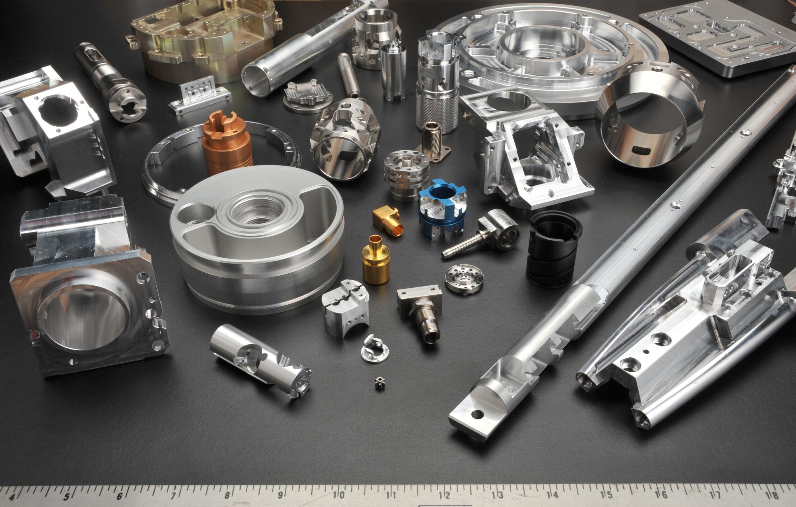
3. Material-Specific Machining Specs
All specs assume optimized tooling, coolant, and process parameters. Honyo Prototype uses:
– Aluminum (6061-T6, 7075):
– Machining: High spindle speeds (15,000–20,000 RPM); 70–100% DOC; dry or mist coolant preferred.
– Tolerance Note: Easy to hold ±0.001″ due to low thermal expansion (12.8 µm/m·°C). Caution: Vibration causes burrs; use sharp tools and light cuts.
– Steel (1018, 4140, 303 SS):
– Machining: Lower speeds (3,000–8,000 RPM); flood coolant essential; carbide tools with TiAlN coating.
– Tolerance Note: Harder to machine; ±0.001″ achievable but requires stress-relieving after roughing. Thermal expansion (6.5 µm/m·°C) is low—ideal for tight tolerances.
– ABS (Acrylonitrile Butadiene Styrene):
– Machining: Low speeds (500–1,500 RPM for turning; 5,000–10,000 RPM for milling); high feed rates; no coolant (causes cracking); use sharp HSS tools.
– Tolerance Note: Prone to thermal distortion (CTE: 50–100 µm/m·°C). Hold ±0.002″ max; avoid aggressive cuts. Store dry to prevent moisture swelling.
– Nylon (6/6, 6/12):
– Machining: Similar to ABS but slower speeds (400–1,200 RPM); use positive-rake tools; avoid heat buildup.
– Tolerance Note*: High moisture absorption (CTE: 80–120 µm/m·°C). Tolerances drift ±0.003″ if not acclimated to lab conditions. Best for non-critical features; use dry machining only.
4. Critical Takeaways for Prototyping Success
- “Tight Tolerance” Requires Holistic Control: It’s not just the machine—it’s tooling, fixturing, thermal management, and process sequencing.
- Example: For a ±0.0005″ hole in steel, we use:
- Drill → ream → honing sequence (not single-pass drilling).
- In-process CMM inspection between operations.
- Temperature-controlled environment (22°C ±1°C).
- 5-Axis ≠ Always Better: Only use 5-axis for geometries requiring <4 setups or complex surfaces. For simple parts, 3-axis is faster/cheaper.
- Plastics Need Special Care: ABS/Nylon tolerances are highly dependent on ambient humidity and cutting heat. Always precondition materials (24h in lab) and use sharp tools to minimize friction.
- Honyo Prototype Standard: We guarantee ±0.001″ on metallic parts (aluminum/steel) for features >0.25″ in size. For plastics, ±0.002″ is standard—tighter tolerances require validation via first-article inspection (FAI).
💡 Pro Tip: For critical tight-tolerance parts, always include a tolerance analysis in your design (e.g., “±0.001″ only on critical features; ±0.005″ elsewhere”). This reduces cost and avoids over-engineering. At Honyo, we offer free DFM (Design for Manufacturing) reviews to optimize this balance.
For project-specific specs, share your part CAD file—we’ll provide a detailed process plan with achievable tolerances, material recommendations, and cost estimates.
From CAD to Part: The Process
Honyo Prototype – “CNC Machine Basics” Workflow
(what happens to every part from the moment you drop a file to the day the courier rings your door-bell)
-
Upload CAD
• Portal accepts any common 3-D format (STEP, IGES, Parasolid, STL, SLDPRT, etc.).
• Geometry is virus-scanned and auto-repaired (healed solids, stitched surfaces, duplicate-face removal).
• A quick “machinability” pre-check runs in the background: is the part larger than 5 mm and smaller than our 1 800 mm travel? Are all faces outward-pointing? If not, the system flags it before you even ask for a quote. -
AI Quote (≤ 5 min)
• Feature-based cost engine reads the solid, not the triangle mesh. It identifies holes, pockets, sculpted surfaces, undercuts, thin walls, deep slots, corner radii, etc.
• It matches every feature to our standard tool library (3-axis, 3+2, 5-axis, live-tool lathe) and selects the cheapest routing that still holds the tolerance you specified.
• Material pricing is pulled from live stock-bar inventory; machine time is multiplied by the exact hourly rate of the spindle group that will be used.
• You see a fully itemised quote: set-up, material, machining, finishing, inspection, shipping. Change quantity, tolerance or surface finish and the price recalculates instantly. -
DFM (Design-for-Manufacturing)
a. Digital DFM report (automated) – generated within 30 min of order placement.
– Recommended cutter access, minimum wall thickness, achievable GD&T, suggested surface finish call-outs.
b. Human DFM review – senior manufacturing engineer opens your part the same day.
– Confirms fixturing strategy: soft-jaw, vacuum, custom Mitee, or zero-point system.
– Decides 3-axis vs 3+2 vs full-5-axis to hit true position call-outs.
– Chooses stock size: oversize allowance ≤ 0.5 mm per side to minimise machine time.
– Adds pick-up geometry, tabs, or micro- bridges if the part is thin-walled.
c. Customer approval loop – you receive a colour PDF + 3-D viewer link; click “Accept” or request changes. No material is cut until you sign off. -
Production
Step 1 – Pre-production
– Work order auto-generated in ERP; bar stock reserved; cutters pre-pulled from crib.
– NC programs created in hyperMILL / Mastercam; tool-list and set-up sheet auto-exported.
Step 2 – Set-up
– Operator loads stock in first-op fixture; probes raw material; sets tool offsets with laser setter (± 5 µm repeatability).
– First-article cut on aluminium or plastic; hardened steel or Ti parts get a “soft” prototype blank first if tolerances are ≤ ± 10 µm.
Step 3 – In-process control
– On-machine probing every 3-5 operations (Renishaw OMP-60) updates cutter wear offsets automatically.
– Critical features checked with 0.5 mm stylus on Zeiss CONTURA CMM; data logged to SPC dashboard.
Step 4 – Secondary & finishing
– De-burr, vapour-blast, anodise, chem-film, passivate, or apply customer-spec coating.
– Laser mark part number, revision, and 2-D data-matrix if required.
Step 5 – Final buy-off
– A-side/B-side inspection report, material cert, coating cert, and CMM bubble chart packaged with the parts.
– Parts vacuum-sealed with desiccant; ESD foam for electronic housings. -
Delivery
• Photos and scan data uploaded to portal; you approve before shipment.
• Default DHL/UPS 2-day; same-day courier available within 200 km of Shenzhen.
• All customs paperwork (COO, HS code, export licence) auto-generated; 97 % of EU/US shipments clear within 3 h.
• Tracking number pushes to your ERP via webhook or e-mail; delivery confirmation triggers invoice auto-release.
That is the entire “CNC machine basics” path at Honyo—upload, AI quote, DFM, production, delivery—turning a CAD solid into a dimensionally certified part on your desk, usually inside 3–5 calendar days.
Start Your Project
Ready to master CNC machine basics? Contact Susan Leo at [email protected] today!
Honyo Prototype • Shenzhen-based manufacturing expertise
🚀 Rapid Prototyping Estimator