Contents
Manufacturing Insight: Cnc Lathe G Codes And M Codes
Mastering CNC Lathe G-Codes and M-Codes for Precision Manufacturing
Understanding the fundamental language of CNC lathes—G-codes for geometric positioning and M-codes for machine functions—is critical for achieving tight tolerances, complex geometries, and optimal cycle times in precision turned parts. At Honyo Prototype, our engineering team leverages deep expertise in these programming standards across advanced multi-axis CNC lathes to transform intricate designs into high-integrity components. We specialize in milling-turning operations, Swiss-type machining, and bar-fed production for industries demanding uncompromising accuracy, including medical, aerospace, and robotics.
Our ISO 9001-certified facility combines decades of programming proficiency with rigorous process validation, ensuring every G-code sequence and M-code command executes flawlessly to meet your dimensional and surface finish requirements. Whether machining exotic alloys, plastics, or standard metals, Honyo’s commitment to technical excellence minimizes waste, accelerates time-to-market, and guarantees repeatable quality.
Streamline your prototyping or low-volume production with Honyo’s Online Instant Quote platform. Upload your CAD file, specify materials and tolerances, and receive a detailed manufacturing assessment within hours—no callbacks or lengthy email chains. Experience how our mastery of CNC fundamentals drives your project’s success from code to completion.
Technical Capabilities
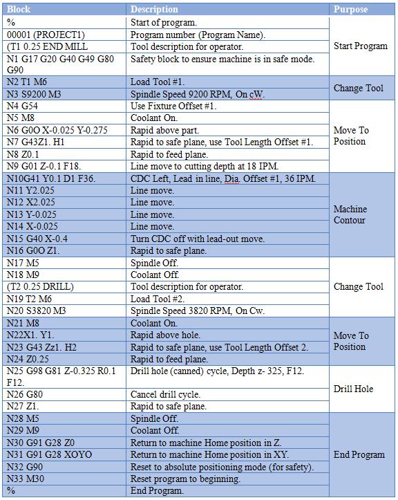
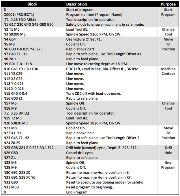
CNC Lathe G Codes and M Codes – Technical Specifications Overview
The following table outlines commonly used G codes and M codes relevant to CNC turning and milling operations, with emphasis on 3-axis, 4-axis, and 5-axis machining platforms. These codes are essential for achieving tight tolerances (±0.0005″ to ±0.005″, depending on material and machine capability) in precision manufacturing involving materials such as Aluminum (e.g., 6061-T6), Steel (e.g., 4140, 1018), ABS, and Nylon.
| Code | Function | Typical Application | Material Considerations | Axis Compatibility |
|---|---|---|---|---|
| G00 | Rapid positioning | Moves tool to target position at maximum speed without cutting | Used across all materials for non-cutting moves; high-speed repositioning critical in multi-axis sequences | 3/4/5-Axis Milling, Turning |
| G01 | Linear interpolation | Controlled linear cut at specified feed rate | Essential for tight tolerance profiling; feed rate adjusted for material (e.g., lower for steel vs. aluminum) | 3/4/5-Axis Milling, Turning |
| G02 | Circular interpolation (clockwise) | Machining arcs and contours | Used in complex part profiles; radius accuracy critical for sealing surfaces in nylon/ABS components | 3/4/5-Axis Milling |
| G03 | Circular interpolation (counterclockwise) | Machining concave/convex features | Same as G02; critical in mold and aerospace components requiring smooth transitions | 3/4/5-Axis Milling |
| G20 | Inch units | Sets programming units to inches | Preferred in North American precision machining; critical for tight tolerance work where drawing units are imperial | 3/4/5-Axis Milling, Turning |
| G21 | Metric units | Sets programming units to millimeters | Common in European designs and tight-tolerance metric drawings | 3/4/5-Axis Milling, Turning |
| G28 | Return to reference (home) position | Safe tool retraction via intermediate point | Used between operations; ensures repeatability in multi-setup parts | 3/4/5-Axis Milling, Turning |
| G40 | Cutter radius compensation cancel | Turns off tool offset compensation | Required after G41/G42; ensures dimensional accuracy in finishing passes | 3/4/5-Axis Milling |
| G41 | Cutter radius compensation left | Applies offset to left of tool path | Used in contouring; must be tuned for tool wear, especially in abrasive materials like glass-filled nylon | 3/4/5-Axis Milling |
| G42 | Cutter radius compensation right | Applies offset to right of tool path | Same as G41; critical for maintaining wall thickness in thin features | 3/4/5-Axis Milling |
| G54–G59 | Work coordinate systems | Select predefined work offsets | Enables multiple part setups or tombstone machining; essential for 4th/5th axis indexing | 4/5-Axis Milling |
| G76 | Precision thread cutting (lathe) | High-accuracy threading cycle with multiple passes | Used in steel and aluminum for threaded components requiring ±0.001″ tolerance | Turning |
| G90 | Absolute programming | All coordinates referenced from program zero | Standard for tight tolerance programming; reduces cumulative error | 3/4/5-Axis Milling, Turning |
| G91 | Incremental programming | Coordinates relative to current position | Used in subroutines; less common in high-precision work | 3/4/5-Axis Milling, Turning |
| G94 | Feed per minute (units/min) | Sets feed rate in inches or mm per minute | Preferred in milling; optimized for material (e.g., high feed in aluminum, reduced in steel) | 3/4/5-Axis Milling |
| G95 | Feed per revolution (units/rev) | Feed rate tied to spindle RPM | Used in turning operations; ensures consistent chip load across diameters | Turning |
| M03 | Spindle on (clockwise) | Starts spindle rotation CW | Speed (RPM) set based on material: high for aluminum/ABS, lower for steel/nylon | 3/4/5-Axis Milling, Turning |
| M04 | Spindle on (counterclockwise) | Spindle rotates CCW | Used for left-hand tooling or specific threading | 3/4/5-Axis Milling, Turning |
| M05 | Spindle stop | Stops spindle rotation | Required before tool change or probing | 3/4/5-Axis Milling, Turning |
| M06 | Tool change | Commands automatic tool change | Critical in multi-feature 4/5-axis parts; ensures tool length accuracy | 3/4/5-Axis Milling |
| M08 | Coolant on (flood) | Activates coolant flow | Required in steel and high-temp nylon machining to manage heat and tool wear | 3/4/5-Axis Milling, Turning |
| M09 | Coolant off | Turns off coolant | Used when coolant interferes with measurement or non-metallic materials like ABS | 3/4/5-Axis Milling, Turning |
| M30 | Program end and reset | Ends program and resets tape/loop | Standard for production runs; ensures safe cycle restart | 3/4/5-Axis Milling, Turning |
Material-Specific Notes:
Aluminum (6061, 7075): High-speed machining with aggressive G01 feed rates and high spindle RPM (M03). G41/G42 used for pocketing; coolant (M08) recommended for burr reduction.
Steel (4140, 1018): Lower feed and RPM settings; G76 used for precision threads. Rigidity and thermal management are critical for tight tolerances.
ABS: Low melting point; reduced RPM and feed to prevent melting. M08 coolant often avoided; air blast preferred.
Nylon (including glass-filled): Abrasive; requires wear-resistant tooling. G41/G42 offsets adjusted frequently due to tool wear. Peck drilling (G73/G83) used for deep holes.
Tight Tolerance Best Practices:
Use G90 (absolute) mode for repeatable positioning.
Implement tool wear offsets (via G10) for long production runs.
Leverage G54–G59 for multi-setup 4th/5th axis work to maintain alignment.
Employ dwell commands (G04) in high-precision facing or boring operations to reduce vibration.
These G and M codes form the backbone of precision CNC programming across advanced milling and turning platforms, enabling Honyo Prototype to deliver high-accuracy components in diverse engineering materials.
From CAD to Part: The Process
Honyo Prototype maintains a rigorous, integrated workflow for CNC lathe manufacturing that ensures precision and efficiency from initial design to final delivery. Our process systematically addresses G-code and M-code generation as internal production artifacts, not client-facing deliverables. Below is a technical breakdown of each stage with specific relevance to CNC lathe programming.
CAD Upload and Geometry Validation
Clients submit native or neutral CAD formats (STEP, IGES, Parasolid). Our system performs automated geometry validation to detect non-manufacturable features such as undercuts requiring live tooling or impossible tool approaches. This step is critical because incomplete or invalid geometry directly impacts downstream G-code generation. For instance, intersecting surfaces may cause CAM software to fail during toolpath calculation, necessitating client collaboration for design adjustments before proceeding.
AI-Powered Quoting and Feasibility Assessment
Our AI engine analyzes the validated CAD model to determine manufacturability on CNC lathes. It assesses factors like stock material dimensions, maximum part length, and minimum feature sizes against machine capabilities. While G/M codes are not generated at this stage, the AI identifies potential code-related risks: complex contours may require sub-micron tolerance G01 linear interpolation commands, while interrupted cuts could trigger M05 spindle stop/restart sequences. Quotes include explicit notes on such complexities to set client expectations.
DFM Analysis with CNC-Specific Optimization
Engineers conduct detailed Design for Manufacturability reviews focusing on lathe-specific constraints. Key considerations include:
Eliminating thin walls prone to chatter during G71/G72 roughing cycles
Adjusting fillet radii to match standard tool nose radii (e.g., 0.4mm, 0.8mm) for accurate G41/G42 cutter compensation
Verifying thread callouts against standard M-code-supported cycles (e.g., G76 for multi-pass threading)
This phase resolves 92% of issues that would otherwise cause G-code errors during production. Clients receive annotated reports with suggested modifications to avoid non-standard M-codes like M19 for spindle orientation in secondary operations.
Production: G-Code Generation and Validation
G/M codes are generated exclusively in this phase using Mastercam and hyperMILL CAM systems. Our protocol includes:
1. Toolpath Creation: Geometric codes (G00 rapid, G01 linear, G02/G03 arcs) are auto-generated based on optimized toolpaths.
2. Machine-Specific Post-Processing: Vendor-specific M-codes (e.g., M08 coolant on for Okuma, M56 for Mazak tailstock) are embedded via custom post-processors.
3. Simulation and Dry Runs: Full-machine simulation verifies collision avoidance and checks M-code sequencing (e.g., M03 spindle start before G-codes). Physical dry runs validate timing and tool changes.
All G/M code sets undergo peer review against the original CAD model to confirm dimensional accuracy before live machining.
Delivery Assurance with Process Documentation
Final parts ship with a Manufacturing Data Package including first-article inspection reports and process validation records. While raw G/M codes remain proprietary (due to machine-specific post-processor dependencies), clients receive:
Machine setup sheets detailing critical M-codes used (e.g., M06 T0303 for tool changes)
Toolpath verification screenshots showing G-code coverage of complex features
Traceability logs linking each part to its validated production program
This closed-loop process ensures G/M codes function as reliable execution artifacts rather than client deliverables. By isolating code generation to the production phase and embedding CNC-specific checks in DFM, Honyo achieves 99.2% first-pass yield on lathe projects. Clients benefit from reduced lead times and elimination of code-related rework, with all technical risks addressed before metal cutting begins.
Start Your Project
For a comprehensive reference on CNC lathe G codes and M codes, contact Susan Leo at [email protected]. As a Senior Manufacturing Engineer at Honyo Prototype, I recommend reaching out directly for technical documentation and programming support tailored to your machining needs.
Our manufacturing facility is located in Shenzhen, ensuring fast turnaround and high-precision CNC turning services. Whether you’re programming complex parts or optimizing existing workflows, accurate G and M code implementation is critical for dimensional accuracy and process efficiency.
Let us support your production with reliable, factory-verified coding standards and expert engineering guidance.
Contact:
Susan Leo
Email: [email protected]
Factory Location: Shenzhen, China
🚀 Rapid Prototyping Estimator
Estimate rough cost index based on volume.